Page 3370 of 4770
EXHAUST GAS RECIRCULATION (EGR) SYSTEM
EC±13
1411 Author�: Date�:
HINT:
As a large amount of e")
B06539
Disconnect
S05567
Air Engine Stopped
S05566
Engine at
2,500 rpm
Air
± EMISSION CONTROL (5S±FE)EXHAUST GAS RECIRCULATION (EGR) SYSTEM
EC±13
1411 Author�: Date�:
HINT:
As a large amount of exhaust gas enters, the engine will misfire
slightly.
(g) Remove the vacuum gauge, and reconnect the vacuum
hoses to the proper locations.
(h) Inspect the EGR valve.
(1) Apply vacuum directly to the EGR valve with the en-
gine idling.
(2) Check that the engine runs rough or dies.
(3) Reconnect the vacuum hoses to the proper loca-
tions.
HINT:
As exhaust gas is increasingly recirculated, the engine will start
to misfire.
(i) Remove the SST from the DLC1.
SST 09843±18020
2. INSPECT EGR VACUUM MODULATOR
(a) Disconnect the vacuum hoses from ports P, Q and R of
the EGR vacuum modulator.
(b) Block ports P and R with your finger.
(c) Blow air into port Q, and check that the air passes through
to the air filter side freely.
(d) Start the engine, and maintain speed at 2,500 rpm.
(e) Repeat the above test. Check that there is a strong resis-
tance to air flow.
(f) Reconnect the vacuum hoses to the proper locations.
Page 3394 of 4770
CO/HC
1174 Author�: Date�:
If the CO/HC concentration does not comply with regulations,
troubleshoot in the order given below.
(1) Check oxygen sensor operation.
(Se")
EM±2
± ENGINE MECHANICAL (5S±FE)CO/HC
1174 Author�: Date�:
If the CO/HC concentration does not comply with regulations,
troubleshoot in the order given below.
(1) Check oxygen sensor operation.
(See page DI±66)
(2) See the table below for possible causes, then in-
spect and correct the applicable causes if neces-
sary.
COHCSymptomCauses
NormalHighRough idle1. Faulty ignitions:
� Incorrect timing
� Fouled, shorted or improperly gapped plugs
� Open or crossed hi
gh±tension cords� Oen or crossed high±tension cords
2. Incorrect valve clearance
3. Leaky EGR valve
4. Leaky intake and exhaust valves
5. Leaky cylinder
LowHighRough idle
(Fluctuating HC reading)1. Vacuum leaks:
� PCV hose
� EGR valve
� Intake manifold
� Throttle body
� IAC valve
� Brake booster line
2. Lean mixture causing misfire
HighHighRough idle
(Black smoke from exhaust)1. Restricted air filter
2. Faulty SFI system
� Faulty pressure regulator
� Defective ECT sensor
� Defective IAT sensor
� Faulty ECM
� Faulty injector
� Faulty throttle position sensor
� MAP sensor
Page 3452 of 4770
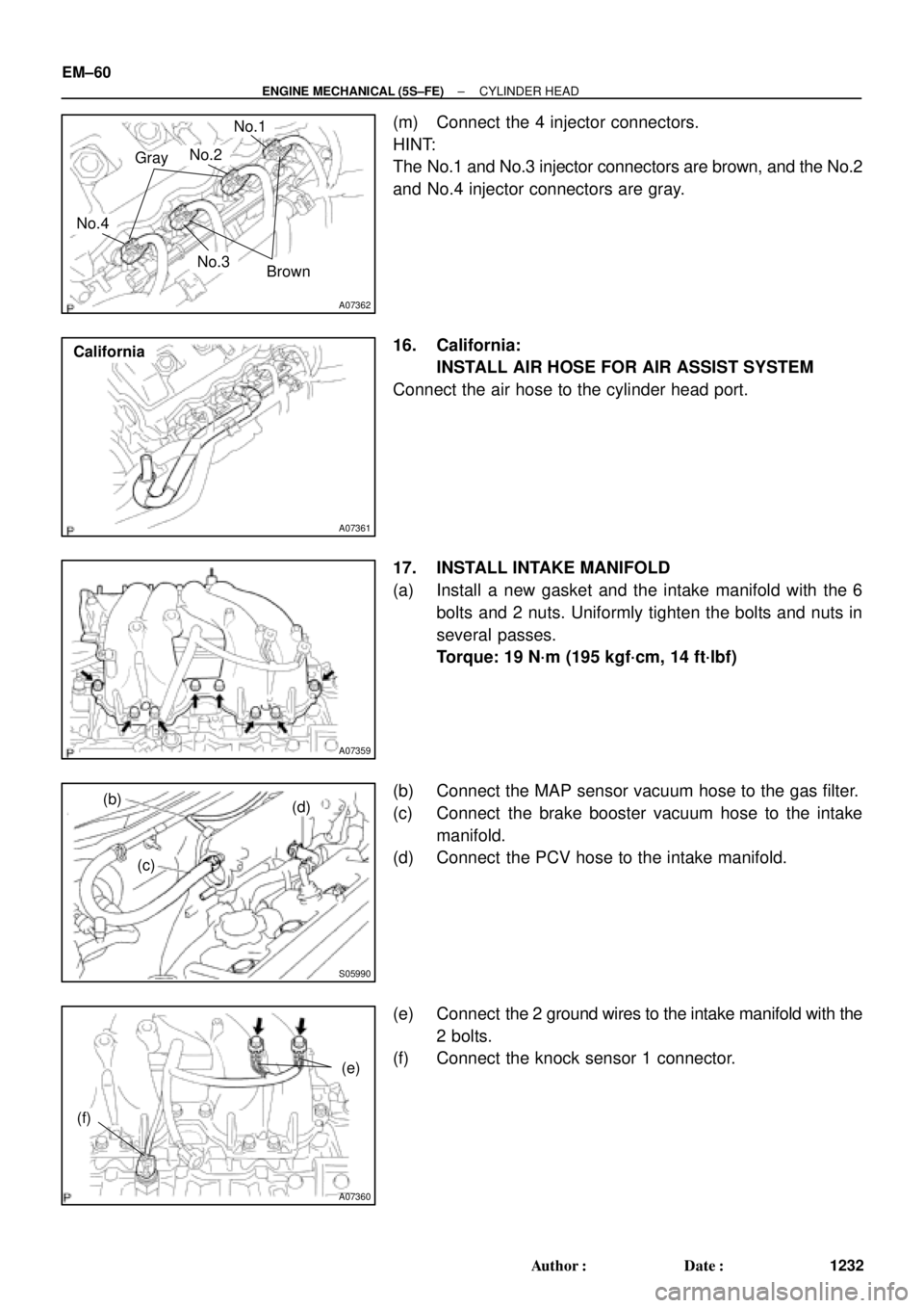
A07362
Gray
Brown
No.1
No.2
No.3
No.4
A07361
California
A07359
S05990
(b)
(c)(d)
A07360
(e)
(f)
EM±60
± ENGINE MECHANICAL (5S±FE)CYLINDER HEAD
1232 Author�: Date�:
(m) Connect the 4 injector connectors.
HINT:
The No.1 and No.3 injector connectors are brown, and the No.2
and No.4 injector connectors are gray.
16. California:
INSTALL AIR HOSE FOR AIR ASSIST SYSTEM
Connect the air hose to the cylinder head port.
17. INSTALL INTAKE MANIFOLD
(a) Install a new gasket and the intake manifold with the 6
bolts and 2 nuts. Uniformly tighten the bolts and nuts in
several passes.
Torque: 19 N´m (195 kgf´cm, 14 ft´lbf)
(b) Connect the MAP sensor vacuum hose to the gas filter.
(c) Connect the brake booster vacuum hose to the intake
manifold.
(d) Connect the PCV hose to the intake manifold.
(e) Connect the 2 ground wires to the intake manifold with the
2 bolts.
(f) Connect the knock sensor 1 connector.
Page 3456 of 4770

EM0YV±01
A02195
Radiator Reservoir Hose
Generator Drive BeltUpper Radiator
Hose
Support BracketFront Exhaust Pipe PS Oil Pressure Switch
ConnectorBattery TrayBattery
PS Pump Drive Belt
PS Pump
Support Stay Upper Radiator Support
Lower Radiator Hose
A/C Compressor
Cylinder Block Insulator
LH Front Fender Apron Seal
Oil Cooler Hose (A/T)
Cruise Control ActuatorEVAP Hose
Air Filter Upper Radiator
Support
EVAP Hose Hood
PCV Hose
Support
Bracket � Gasket
�
� Non±reusable part� Gasket
�Clamp
N´m (kgf´cm, ft´lbf)
62 (630, 46)
56 (570, 41)
�
: Specified torque
Washer Hose
for Windshield
No.1 Electric
Cooling Fan
Connector
ECT Switch
Connector No.2 Electric
Cooling Fan
ConnectorRadiator
Assembly
A/C Compressor
ConnectorLower Radiator
Support
RH Front Fender
Aplon Seal
Cruise
Control
Actuator
Connector
Battery
Hold±Down
ClampAir Cleaner
Case
VSV
Connector
for EVAP
EVAP
Hose
IAT Sensor
Connector
Air
Cleaner
Cap
EM±64
± ENGINE MECHANICAL (5S±FE)ENGINE UNIT
1236 Author�: Date�:
ENGINE UNIT
COMPONENTS
Page 3461 of 4770
ENGINE UNIT
EM±69
1241 Author�: Date�:
REMOVAL
1. REMOVE HOOD
2. REMOVE FRONT FENDER APRON SEALS
3. DRAIN ENGINE COOLANT
4. DRAIN ENGINE OIL
5. DISCONNEC")
EM08F±04
S05251
± ENGINE MECHANICAL (5S±FE)ENGINE UNIT
EM±69
1241 Author�: Date�:
REMOVAL
1. REMOVE HOOD
2. REMOVE FRONT FENDER APRON SEALS
3. DRAIN ENGINE COOLANT
4. DRAIN ENGINE OIL
5. DISCONNECT ACCELERATOR CABLE
6. REMOVE AIR CLEANER CAP
(a) Disconnect the IAT sensor connector.
(b) Disconnect the VSV connector for the EVAP
(c) Disconnect the PCV hose from the cylinder head cover.
(d) Disconnect the EVAP hose from the throttle body.
(e) Disconnect the EVAP hose from the VSV.
(f) Disconnect the 2 clamps, and disconnect the air cleaner
cap from the air cleaner case.
(g) Loosen hose clamp, and disconnect the air cleaner hose
from the throttle body.
(h) Remove the air cleaner cap and hose assembly.
7. REMOVE AIR CLEANER CASE
(a) Remove the air filter.
(b) Remove the 3 bolts and air cleaner case.
8. REMOVE BATTERY AND TRAY
9. REMOVE CRUISE CONTROL ACTUATOR
10. REMOVE RADIATOR (See page CO±18)
11. REMOVE FRONT EXHAUST PIPE
(a) Remove the 2 bolts holding the support stay to the sup-
port bracket.
(b) Remove the 2 bolts holding the support bracket to the
front frame.
(c) Remove the 2 bolts and 2 nuts holding the front exhaust
pipe to the center exhaust pipe.
(d) Remove the 3 nuts holding the front exhaust pipe to the
exhaust manifold.
(e) Remove the front exhaust pipe and 2 gaskets.
(f) Remove the nut and support bracket.
12. DISCONNECT CONNECTORS, WIRES, CABLES,
CLAMPS AND HOSES
(a) Disconnect the generator wire.
(b) Disconnect the generator connector.
(c) Disconnect the wire clamp from the generator.
(d) Disconnect the starter cable.
(e) Disconnect the starter connector.
(f) Disconnect the DLC1 from the bracket.
Page 3472 of 4770
ENGINE UNIT
1252 Author�: Date�:
(b) Connect the generator connector.
(c) Install the wire clamp to the generator.
(d) Connect the starter cable.
(e) Connect")
S05251
EM±80
± ENGINE MECHANICAL (5S±FE)ENGINE UNIT
1252 Author�: Date�:
(b) Connect the generator connector.
(c) Install the wire clamp to the generator.
(d) Connect the starter cable.
(e) Connect the starter connector.
(f) Install the DLC1 to the bracket.
(g) Install the engine wire clamp to the bracket on the RH
fender apron.
(h) Connect the MAP sensor connector.
(i) Install the wire clamp to the bracket for the MAP sensor.
(j) Connect the VSV connector for the vapor pressure sen-
sor.
(k) Connect the 2 ground strap connectors to the RH fender
apron.
(l) Connect the 2 ground strap connectors to the LH fender
apron.
(m) Install the engine wire protector clamp to the battery
bracket.
(n) Install the engine wire to the clamp on the fuel filter.
(o) Connect the ground cable to the transaxle.
(p) Connect the brake booster vacuum hose to the intake
manifold.
(q) Connect the heater hose to the water outlet.
(r) Connect the heater hose to the water bypass pipe.
(s) Connect the fuel inlet hose to the fuel filter with 2 new gas-
kets and the union bolt.
Torque: 29 N´m (300 kgf´cm, 21 ft´lbf)
(t) Connect the MAP sensor vacuum hose to the gas filter on
the intake manifold.
33. INSTALL FRONT EXHAUST PIPE
(a) Install the support bracket with the nut.
Torque: 33 N´m (330 kgf´cm, 24 ft´lbf)
(b) Temporarily install 2 new gaskets and the front exhaust
pipe with the 2 bolts and 5 nuts.
(c) Tighten the 3 nuts holding the exhaust manifold to the
front exhaust pipe.
Torque: 62 N´m (630 kgf´cm, 46 ft´lbf)
(d) Tighten the 2 bolts and 2 nuts holding the front exhaust
pipe to the center exhaust pipe.
Torque: 56 N´m (570 kgf´cm, 41 ft´lbf)
(e) Install the bracket with the 2 bolts.
Torque: 33 N´m (330 kgf´cm, 24 ft´lbf)
(f) Install the support stay with the 2 bolts.
Torque: 33 N´m (330 kgf´cm, 24 ft´lbf)
34. INSTALL RADIATOR (See page CO±23)
35. INSTALL CRUISE CONTROL ACTUATOR
36. INSTALL BATTERY TRAY AND BATTERY
37. INSTALL AIR CLEANER CASE
Install the air cleaner case with the 3 bolts.
Page 3508 of 4770
CO/HC
1288 Author�: Date�:
If the CO/HC concentration dose not comply with regulations,
troubleshoot in the order given below.
See the table below for possible caus")
EM±2
± ENGINE MECHANICAL (1MZ±FE)CO/HC
1288 Author�: Date�:
If the CO/HC concentration dose not comply with regulations,
troubleshoot in the order given below.
See the table below for possible causes, then inspect and cor-
rect the applicable causes if necessary.
COHCProblemsCauses
NormalHighRough idle1. Faulty ignitions:
�Incorrect timin
g�Incorrect timing
�Fouled, shorted or improperly gapped plugs
�Open or crossed hi
gh±tension cords�Oen or crossed high±tension cords
2. Incorrect valve clearance
3 Leaky EGR valve
3 Leaky EGR valve
4.Leaky intake and exhaust valves
5.Leaky cylinder
LowHighRough idle1. Vacuum leaks:LowHighRough idle
(
Filtrating HC reading)
1. Vacuum leaks:
�PCV hose(Filtrating HC reading)�PCV hose
�EGR valve�EGR valve
�Intake manifold�Intake manifold
�Air intake chamber�Air intake chamber
�Throttle bodyThrottle body
�IAC valveIAC valve
�Brake booster lineBrake booster line
2. Lean mixture causing misfire
HighHighRough idle
(Black smoke from exhaust)1. Restricted air filter
2. Faulty SFI system
�Faulty pressure regulator
�Defective ECT sensor
�Faulty ECM
�Faulty injectors
�Faulty throttle position sensor
�Faulty MAF meter
Page 3533 of 4770
EM04R±05
A06651
RH Fender Apron Seal
Generator
Drive Belt
RH Engine Mounting Stay
No.2 RH Engine
Mounting BracketMAF Meter
Connector
EVAP Hose
Air Cleaner
Cap Assembly
Air Filter
EGR Vacuum Hose PS Pump Drive Belt
PS Pump
No.2 RH Engine
Mounting Stay (M/T)
�
� StayBracketFront Exhaust Pipe
� Non±reusable part: Specified torque
� Gasket
� Gasket� Gasket
64 (650, 47)32 (320, 23)
43 (440, 32)
62 (630, 46)
33 (330, 24)
64 (650, 47)
62 (630, 46)
33 (330, 24)
56 (570, 41)
N´m (kgf´cm, ft´lbf)
± ENGINE MECHANICAL (1MZ±FE)CYLINDER HEAD
EM±27
1313 Author�: Date�:
CYLINDER HEAD
COMPONENTS