Page 123 of 4770
10. INSTALL GENERATOR BRACKET
Install the generator bracket with the 3 bolts.
Torque: 42 N±m (425 kgf±cm, 31 ft±lbf)
11. INSTALL ENGINE HANGERS
Install the engine hanger with the bolt. Install the 2
engine hangers. Install the ground strap.
Torque: 25 N±m (250 kgf±cm, 18 ft±lbf)
(c) Install the gasket to the head cover.
(d) Install the head cover with the 4 grommets and nuts.
Uniformly tighten the nuts in several passes.
Torque: 23 N±m (230 kgf±cm, 17 ft±lbf)
HINT: Install the grommets so that their markings are
as shown in the illustration.
9. INSTALL OIL PRESSURE SWITCH
Apply adhesive to 2 or 3 threads.
Adhesive:
Part No.08833±00080, THREE BOND 1324 or equivalent
12. INSTALL NO.3 TIMING BELT COVER
Install the timing belt cover with the 4 bolts.
Torque: 7.8 N±m (80 kgf±cm, 69 in±lbf)
± 5S±FE ENGINEENGINE MECHANICALEG1±73
Page 130 of 4770
31. ASSEMBLE EXHAUST MANIFOLD AND WARM UP
THREE±WAY CATALYTIC CONVERTER
Assemble the following parts:
(1) WU±TWC
(2) Cushion
(3) Retainer
(4) Gasket
(5) Exhaust manifold
(6) 3 bolts and 2 nuts
Torque: 29 N±m (300 kgf±cm, 22 ft±lbf)
(c) Connect the following connectors:
(1) Engine coolant temperature sender gauge con±
nector
(2) Engine coolant temperature sensor connector
29. CONNECT ENGINE WIRE (FOR OXYGEN SENSORS)
TO ENGINE HANGER
30. CONNECT OIL PRESSURE SWITCH CONNECTOR
32. INSTALL EXHAUST MANIFOLD AND WARM UP
THREE±WAY CATALYTIC CONVERTER
ASSEMBLY
(a) Install a new gasket, the exhaust manifold and WU ±
TWC assembly with the 6 nuts. Uniformly tighten the
nuts in several passes.
Torque: 49 N±m (540 kgf±cm, 36 ft±lbf)
(7) 2 converter heat insulators
(8) 8 bolts
(9) Manifold lower heat insulator
(10) 3 bolts
± 5S±FE ENGINEENGINE MECHANICALEG1±80
Page 322 of 4770

OIL PRESSURE CHECK
1. CHECK ENGINE OIL QUALITY
Check the oil for deterioration, entry of water, dis±
coloring or thinning.
If the quality is visibly poor, replace the oil.
Oil grade:
API grade SG or SH, Energy Conserving II multi±
grade engine oil or ILSAC multigrade engine oil.
Recommended viscosity is as shown in the illustra±
tion.
2. CHECK ENGINE OIL LEVEL
The oil level should be between the ªLº and ªFº marks
on the dipstick.
If low, check for leakage and add oil up to ªFº mark.
3. REMOVE OIL PRESSURE SWITCH, AND INSTALL
OIL PRESSURE GAUGE
4. WARM UP ENGINE
Allow the engine to warm up to normal operating
temperature.
5. CHECK OIL PRESSURE
Oil pressure:
At idle
29 kPa (0.3 kgf/cm�, 4.3 psi) or more
At 3,000 rpm
245 ± 490 kPa (2.5 ± 5.0 kg f/cm�, 36 ± 71 psi)
NOTICE:
wWhen inserting the oil dipstick, insert the curved tip
of the dipstick facing the same direction as the
curve of the guide.
wIf the dipstick gets caught while inserting it, do not
force it in. Reconfirm the direction of the dipstick.
± 5S±FE ENGINELUBRICATION SYSTEMEG1±272
Page 323 of 4770
6. REMOVE OIL PRESSURE GAUGE AND REINSTALL
OIL PRESSURE SWITCH
(a) Remove the oil pressure gauge.
(b) Apply adhesive to 2 or 3 threads of the oil pressure
switch.
Adhesive:
Part No.08833 ± 00080, THREE BOND 1344,
LOCTITE 242 or equivalent
(c) Reinstall the oil pressure switch.
7. START ENGINE AND CHECK FOR LEAKS
± 5S±FE ENGINELUBRICATION SYSTEMEG1±273
Page 1590 of 4770
AC0N3±02
N20292
AC±68
± AIR CONDITIONINGPRESSURE SWITCH
2550 Author�: Date�:
REMOVAL
1. DISCHARGE REFRIGERANT FROM REFRIGERATION
SYSTEM
HINT:
At the time of installation, please refer to the following item.
Evacuate air from refrigeration system.
Charge system with refrigerant and inspect for leakage of refrig-
erant.
Specified amount: 800 ± 50 g (28.22 ± 1.76 oz.)
2. REMOVE PRESSURE SWITCH FROM LIQUID TUBE
Disconnect the connector and remove the pressure switch.
Torque: 10 N´m (100 kgf´cm, 7 ft´lbf)
HINT:
�Lock the switch mount on the tube with an open end
wrench, being careful not to deform the tube, and remove
the switch.
�At the time of installation, please refer to the following
item.
Lubricate a new O±ring with the compressor oil and install
the switch.
Page 3429 of 4770

A02593
S05933
P03355
10 ± 45°
Knock
Pin
± ENGINE MECHANICAL (5S±FE)CYLINDER HEAD
EM±37
1209 Author�: Date�:
NOTICE:
�Support the timing belt, so the meshing of the crank-
shaft timing pulley and timing belt does not shift.
�Be careful not to drop anything inside the timing belt
cover.
�Do not allow the belt to come into contact with oil, wa-
ter or dust.
21. REMOVE ENGINE HANGERS AND GENERATOR
BRACKET
(a) Remove the 3 bolts, the generator bracket and RH engine
hanger assembly.
(b) Remove the bolt and LH engine hanger.
22. REMOVE OIL PRESSURE SWITCH
23. REMOVE CYLINDER HEAD COVER
Remove the 4 nuts, grommets, head cover and gasket.
HINT:
Arrange the grommets in the correct order, so that they can be
reinstalled into their original positions. This minimizes any pos-
sibility of oil leakage due to reuse of the grommets in different
positions.
24. REMOVE CAMSHAFTS
NOTICE:
Since the thrust clearance of the camshaft is small, the
camshaft must be kept level while it is being removed. If the
camshaft is not kept level, the portion of the cylinder head
receiving the shaft thrust may crack or be damaged, caus-
ing the camshaft to seize or break. To avoid this, the follow-
ing steps should be carried out.
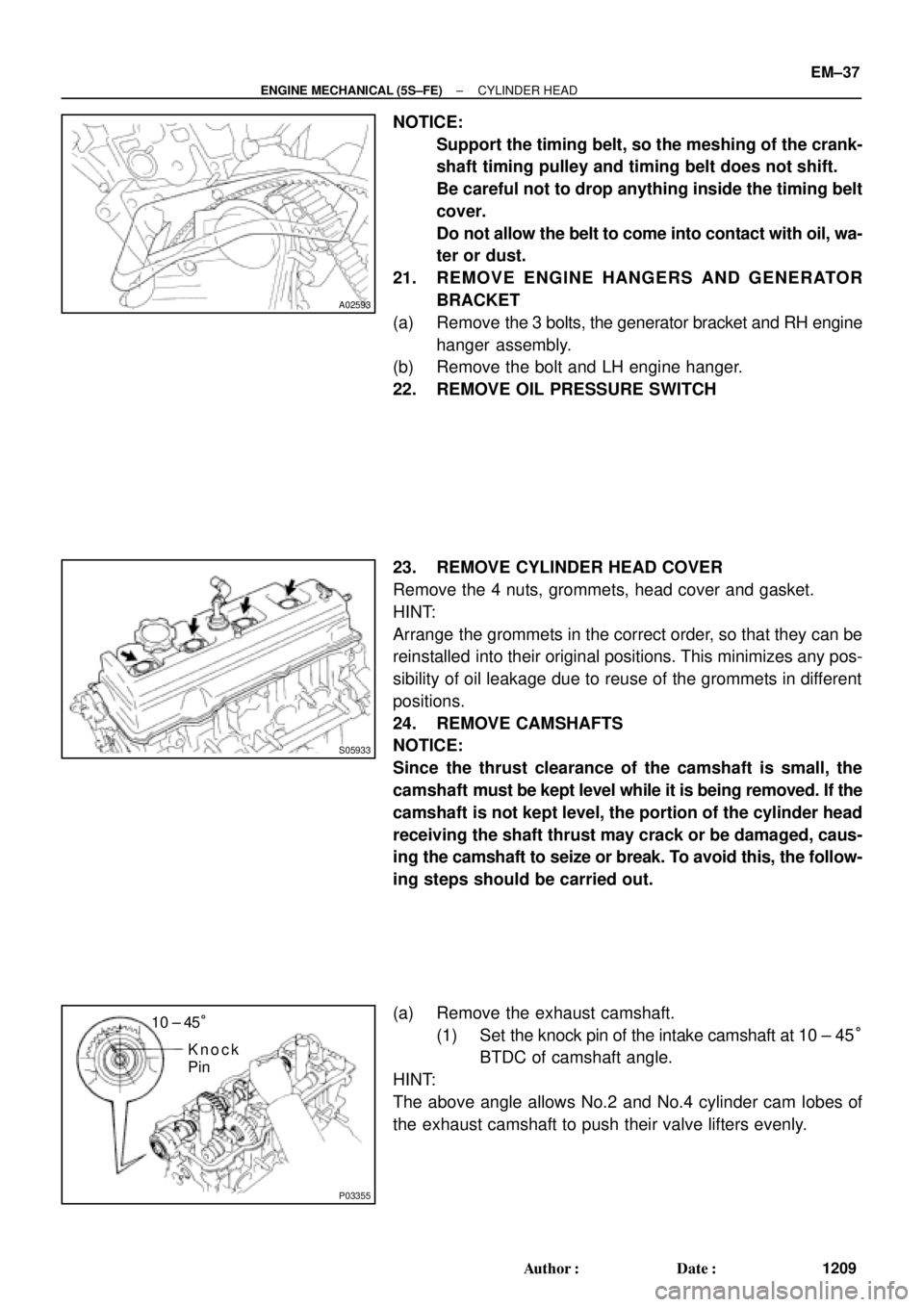
(a) Remove the exhaust camshaft.
(1) Set the knock pin of the intake camshaft at 10 ± 45°
BTDC of camshaft angle.
HINT:
The above angle allows No.2 and No.4 cylinder cam lobes of
the exhaust camshaft to push their valve lifters evenly.
Page 3450 of 4770

P13638
Adhesive
S05962
Z09141
California
Except California New O±RingNew Insulator
New GrommetNew O±Ring
New GrommetNew
O±Ring EM±58
± ENGINE MECHANICAL (5S±FE)CYLINDER HEAD
1230 Author�: Date�:
9. INSTALL OIL PRESSURE SWITCH
(a) Apply adhesive to 2 or 3 threads.
Adhesive:
Part No. 08833±00080, THREE BOND 1324 or equiva-
lent
(b) Install the oil pressure switch.
10. INSTALL ENGINE HANGERS AND GENERATOR
BRACKET
(a) Install the generator bracket and RH engine hanger as-
sembly with the 3 bolts.
Torque: 42 N´m (425 kgf´cm, 31 ft´lbf)
(b) Install the LH engine hanger with the bolt.
Torque: 25 N´m (250 kgf´cm, 18 ft´lbf)
11. INSTALL NO.3 TIMING BELT COVER
Install the timing belt cover with the 3 bolts.
Torque: 7.8 N´m (80 kgf´cm, 69 in.´lbf)
12. TEMPORARILY INSTALL NO.1 IDLER PULLEY AND
TENSION SPRING (See page EM±23)
13. INSTALL CAMSHAFT TIMING PULLEY
(See page EM±23)
14. CONNECT TIMING BELT TO CAMSHAFT TIMING
PULLEY (See page EM±23)
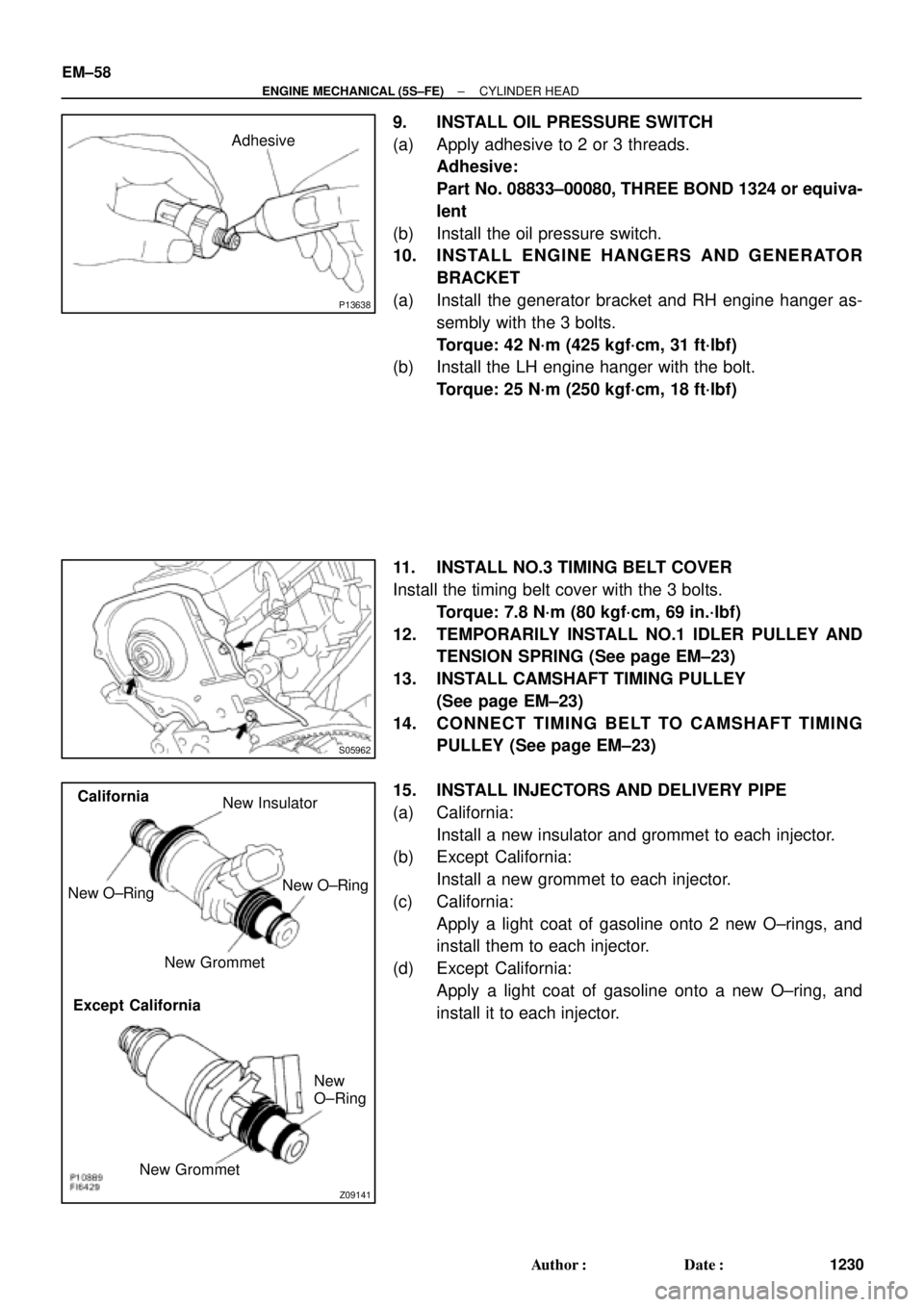
15. INSTALL INJECTORS AND DELIVERY PIPE
(a) California:
Install a new insulator and grommet to each injector.
(b) Except California:
Install a new grommet to each injector.
(c) California:
Apply a light coat of gasoline onto 2 new O±rings, and
install them to each injector.
(d) Except California:
Apply a light coat of gasoline onto a new O±ring, and
install it to each injector.
Page 3453 of 4770

S05982
SST
Fulcrum
Length
A07365
A07363
A07364
Clamp
Connector
A01564(b)(c)(d)
± ENGINE MECHANICAL (5S±FE)CYLINDER HEAD
EM±61
1233 Author�: Date�:
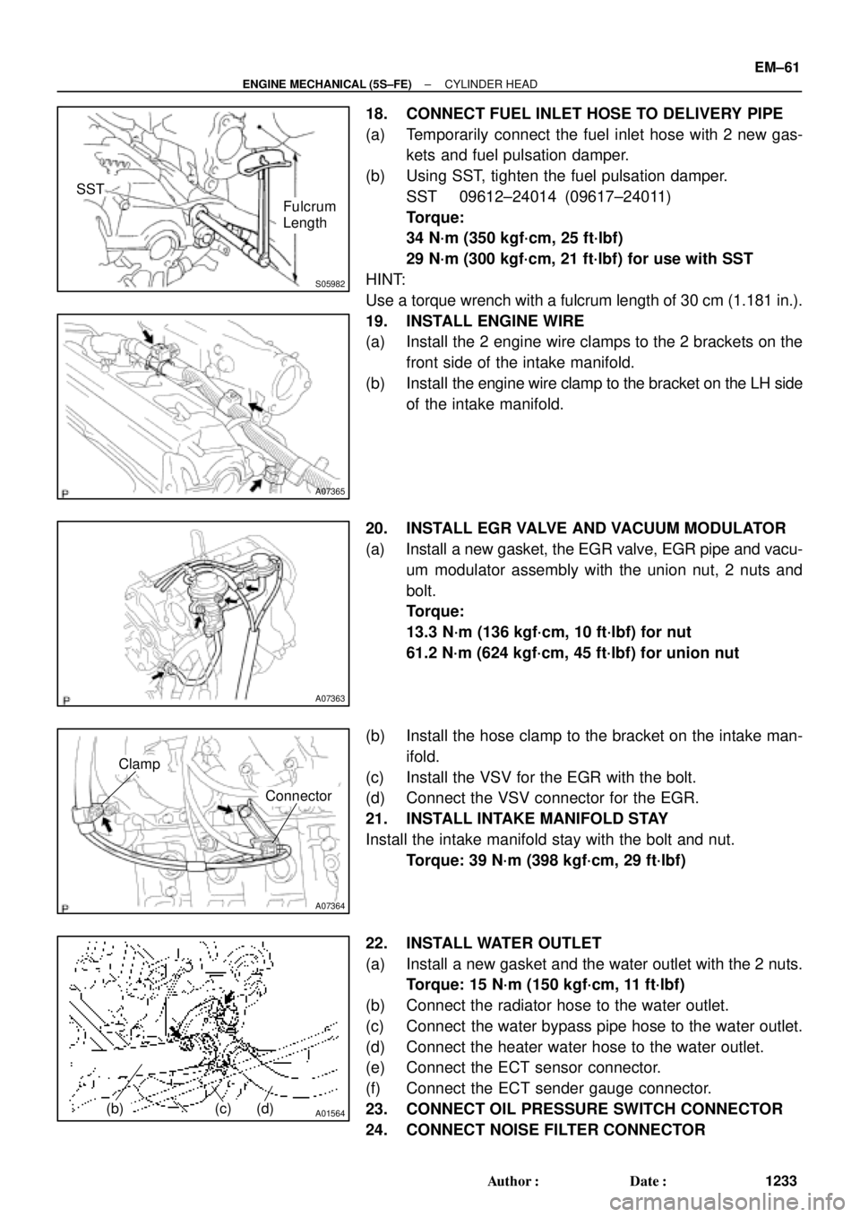
18. CONNECT FUEL INLET HOSE TO DELIVERY PIPE
(a) Temporarily connect the fuel inlet hose with 2 new gas-
kets and fuel pulsation damper.
(b) Using SST, tighten the fuel pulsation damper.
SST 09612±24014 (09617±24011)
Torque:
34 N´m (350 kgf´cm, 25 ft´lbf)
29 N´m (300 kgf´cm, 21 ft´lbf) for use with SST
HINT:
Use a torque wrench with a fulcrum length of 30 cm (1.181 in.).
19. INSTALL ENGINE WIRE
(a) Install the 2 engine wire clamps to the 2 brackets on the
front side of the intake manifold.
(b) Install the engine wire clamp to the bracket on the LH side
of the intake manifold.
20. INSTALL EGR VALVE AND VACUUM MODULATOR
(a) Install a new gasket, the EGR valve, EGR pipe and vacu-
um modulator assembly with the union nut, 2 nuts and
bolt.
Torque:
13.3 N´m (136 kgf´cm, 10 ft´lbf) for nut
61.2 N´m (624 kgf´cm, 45 ft´lbf) for union nut
(b) Install the hose clamp to the bracket on the intake man-
ifold.
(c) Install the VSV for the EGR with the bolt.
(d) Connect the VSV connector for the EGR.
21. INSTALL INTAKE MANIFOLD STAY
Install the intake manifold stay with the bolt and nut.
Torque: 39 N´m (398 kgf´cm, 29 ft´lbf)
22. INSTALL WATER OUTLET
(a) Install a new gasket and the water outlet with the 2 nuts.
Torque: 15 N´m (150 kgf´cm, 11 ft´lbf)
(b) Connect the radiator hose to the water outlet.
(c) Connect the water bypass pipe hose to the water outlet.
(d) Connect the heater water hose to the water outlet.
(e) Connect the ECT sensor connector.
(f) Connect the ECT sender gauge connector.
23. CONNECT OIL PRESSURE SWITCH CONNECTOR
24. CONNECT NOISE FILTER CONNECTOR