Page 3471 of 4770

S04616
A/T
S05246
S05250
Connector
S05253
± ENGINE MECHANICAL (5S±FE)ENGINE UNIT
EM±79
1251 Author�: Date�:
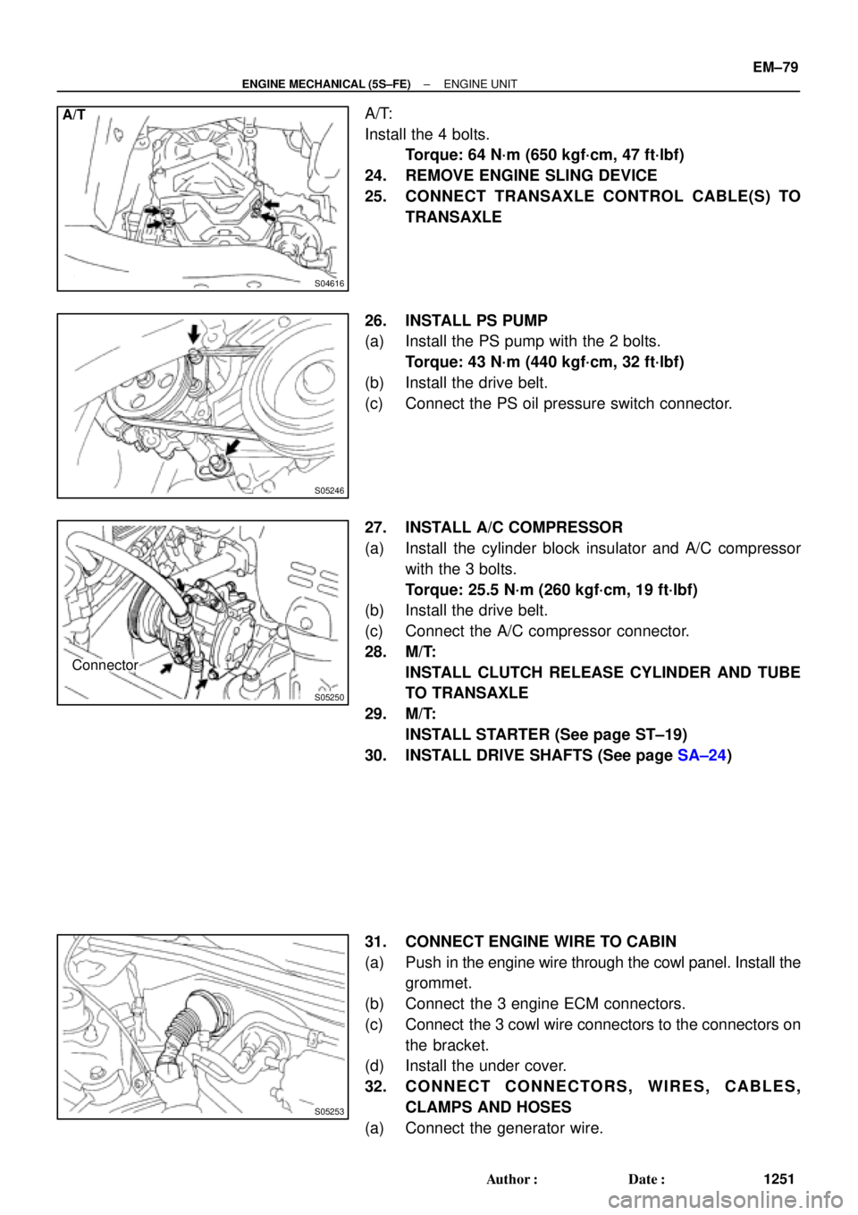
A/T:
Install the 4 bolts.
Torque: 64 N´m (650 kgf´cm, 47 ft´lbf)
24. REMOVE ENGINE SLING DEVICE
25. CONNECT TRANSAXLE CONTROL CABLE(S) TO
TRANSAXLE
26. INSTALL PS PUMP
(a) Install the PS pump with the 2 bolts.
Torque: 43 N´m (440 kgf´cm, 32 ft´lbf)
(b) Install the drive belt.
(c) Connect the PS oil pressure switch connector.
27. INSTALL A/C COMPRESSOR
(a) Install the cylinder block insulator and A/C compressor
with the 3 bolts.
Torque: 25.5 N´m (260 kgf´cm, 19 ft´lbf)
(b) Install the drive belt.
(c) Connect the A/C compressor connector.
28. M/T:
INSTALL CLUTCH RELEASE CYLINDER AND TUBE
TO TRANSAXLE
29. M/T:
INSTALL STARTER (See page ST±19)
30. INSTALL DRIVE SHAFTS (See page SA±24)
31. CONNECT ENGINE WIRE TO CABIN
(a) Push in the engine wire through the cowl panel. Install the
grommet.
(b) Connect the 3 engine ECM connectors.
(c) Connect the 3 cowl wire connectors to the connectors on
the bracket.
(d) Install the under cover.
32. CONNECT CONNECTORS, WIRES, CABLES,
CLAMPS AND HOSES
(a) Connect the generator wire.
Page 3589 of 4770
EM051±04
S04921
P12946
P18761
P12389
SST
± ENGINE MECHANICAL (1MZ±FE)CYLINDER BLOCK
EM±83
1369 Author�: Date�:
DISASSEMBLY
1. M/T:
REMOVE FLYWHEEL
2. A/T:
REMOVE DRIVE PLATE
3. INSTALL ENGINE TO ENGINE STAND FOR
DISASSEMBLY
4. REMOVE TIMING BELT AND PULLEYS
(See page EM±15)
5. REMOVE CYLINDER HEAD (See page EM±32)
6. REMOVE GENERATOR, ADJUSTING BAR AND
BRACKET ASSEMBLY
(a) Disconnect the 2 wire clamps from the wire brackets.
(b) Remove the 3 nuts, the generator, adjusting bar and
bracket assembly.
7. REMOVE OIL PRESSURE SWITCH
(See page LU±1)
8. REMOVE A/C COMPRESSOR HOUSING BRACKET
Remove the 3 bolts and compressor housing bracket.
9. REMOVE NO.2 IDLER PULLEY BRACKET
Remove the 2 bolts and idler pulley bracket.
10. REMOVE KNOCK SENSORS
(a) Disconnect the 2 knock sensor connectors.
(b) Using SST, remove the 2 knock sensors.
SST 09816±30010
Page 3616 of 4770
P00601
Adhesive
A05416
1
2 34 5
67
8
EM±110
± ENGINE MECHANICAL (1MZ±FE)CYLINDER BLOCK
1396 Author�: Date�:
30. INSTALL OIL PRESSURE SWITCH
(See page LU±1)
31. INSTALL GENERATOR, BRACKET AND
ADJUSTING BAR ASSEMBLY
Torque: 43 N´m (440 kgf´cm, 32 ft´lbf)
32. INSTALL CYLINDER HEAD (See page EM±57)
33. INSTALL TIMING PULLEYS AND BELT
(See page EM±21)
34. REMOVE ENGINE STAND
35. A/T:
INSTALL DRIVE PLATE
(a) Apply adhesive to 2 or 3 threads of the bolt end.
Adhesive: Part No. 08833±00070, THREE BOND 1324
or equivalent
(b) Install the front spacer, drive plate and rear plate on the
crankshaft.
(c) Install and uniformly tighten the 8 bolts, in several passes,
in the sequence shown.
Torque: 83 N´m (850 kgf´cm, 61 ft´lbf)
36. M/T:
INSTALL FLYWHEEL (See step 35)
Torque: 83 N´m (850 kgf´cm, 61 ft´lbf)
Page 3715 of 4770

B00319
Recommended Viscosity (SAE) :
TEMPERATURE RANGE ANTICIPATED BEFORE NEXT OIL CHANGE 10W ± 30
5W ± 30 PREFERRED
±20
°C °F020406080
±29 ±18 ±7 4 16 27100
38
LU03H±03
S05317
Curved
Tip
Insert
S05298
Oil Pressure Gauge
P13638
Adhesive
± LUBRICATION (5S±FE)OIL AND FILTER
LU±1
1647 Author�: Date�:
OIL AND FILTER
INSPECTION
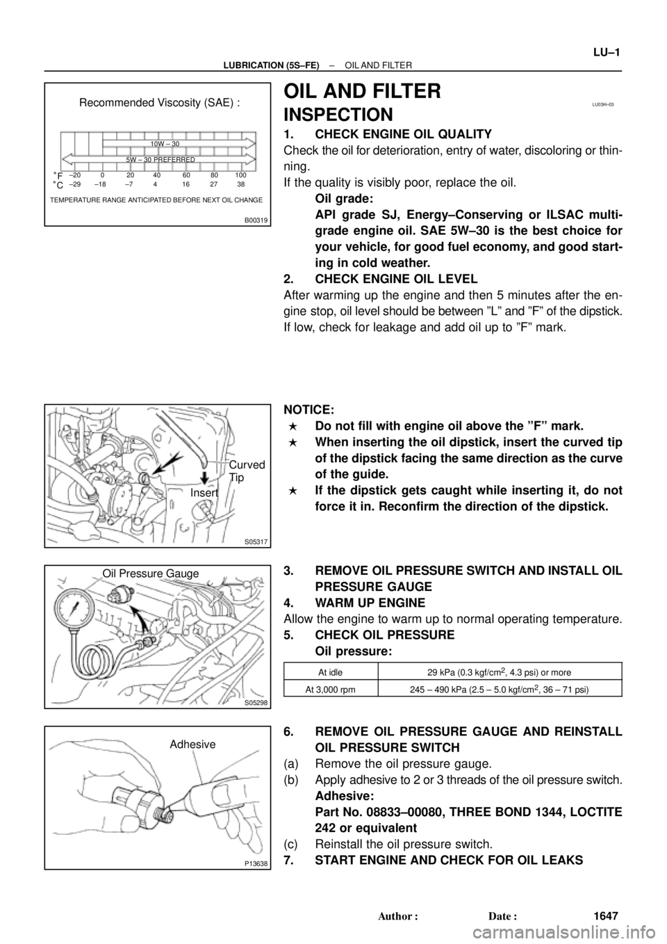
1. CHECK ENGINE OIL QUALITY
Check the oil for deterioration, entry of water, discoloring or thin-
ning.
If the quality is visibly poor, replace the oil.
Oil grade:
API grade SJ, Energy±Conserving or ILSAC multi-
grade engine oil. SAE 5W±30 is the best choice for
your vehicle, for good fuel economy, and good start-
ing in cold weather.
2. CHECK ENGINE OIL LEVEL
After warming up the engine and then 5 minutes after the en-
gine stop, oil level should be between ºLº and ºFº of the dipstick.
If low, check for leakage and add oil up to ºFº mark.
NOTICE:
�Do not fill with engine oil above the ºFº mark.
�When inserting the oil dipstick, insert the curved tip
of the dipstick facing the same direction as the curve
of the guide.
�If the dipstick gets caught while inserting it, do not
force it in. Reconfirm the direction of the dipstick.
3. REMOVE OIL PRESSURE SWITCH AND INSTALL OIL
PRESSURE GAUGE
4. WARM UP ENGINE
Allow the engine to warm up to normal operating temperature.
5. CHECK OIL PRESSURE
Oil pressure:
At idle29 kPa (0.3 kgf/cm2, 4.3 psi) or more
At 3,000 rpm245 ± 490 kPa (2.5 ± 5.0 kgf/cm2, 36 ± 71 psi)
6. REMOVE OIL PRESSURE GAUGE AND REINSTALL
OIL PRESSURE SWITCH
(a) Remove the oil pressure gauge.
(b) Apply adhesive to 2 or 3 threads of the oil pressure switch.
Adhesive:
Part No. 08833±00080, THREE BOND 1344, LOCTITE
242 or equivalent
(c) Reinstall the oil pressure switch.
7. START ENGINE AND CHECK FOR OIL LEAKS
Page 3733 of 4770

B00319
Recommended Viscosity (SAE):
TEMPERATURE RANGE ANTICIPATED BEFORE NEXT OIL CHANGE10W±30
5W±30 PREFERRED°C °F
±20
±290
±1820
±740
460
1680
27100
38
LU0FR±01
P25173SST
P25171
Oil Pressure Gauge
± LUBRICATION (1MZ±FE)OIL AND FILTER
LU±1
1665 Author�: Date�:
OIL AND FILTER
INSPECTION
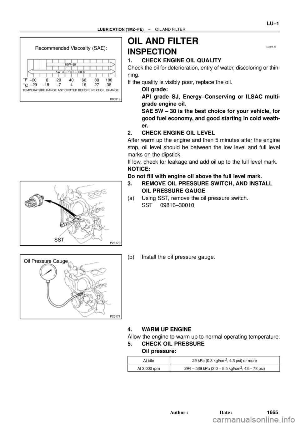
1. CHECK ENGINE OIL QUALITY
Check the oil for deterioration, entry of water, discoloring or thin-
ning.
If the quality is visibly poor, replace the oil.
Oil grade:
API grade SJ, Energy±Conserving or ILSAC multi-
grade engine oil.
SAE 5W ± 30 is the best choice for your vehicle, for
good fuel economy, and good starting in cold weath-
er.
2. CHECK ENGINE OIL LEVEL
After warm up the engine and then 5 minutes after the engine
stop, oil level should be between the low level and full level
marks on the dipstick.
If low, check for leakage and add oil up to the full level mark.
NOTICE:
Do not fill with engine oil above the full level mark.
3. REMOVE OIL PRESSURE SWITCH, AND INSTALL
OIL PRESSURE GAUGE
(a) Using SST, remove the oil pressure switch.
SST 09816±30010
(b) Install the oil pressure gauge.
4. WARM UP ENGINE
Allow the engine to warm up to normal operating temperature.
5. CHECK OIL PRESSURE
Oil pressure:
At idle29 kPa (0.3 kgf/cm2, 4.3 psi) or more
At 3,000 rpm294 ± 539 kPa (3.0 ± 5.5 kgf/cm2, 43 ± 78 psi)
Page 3734 of 4770
P12478
Adhesive
LU±2
± LUBRICATION (1MZ±FE)OIL AND FILTER
1666 Author�: Date�:
6. REMOVE OIL PRESSURE GAUGE AND REINSTALL
OIL PRESSURE SWITCH
(a) Remove the oil pressure gauge.
(b) Apply adhesive to 2 or 3 threads of the oil pressure switch.
Adhesive: Part No. 08833±00080, THREE BOND 1344,
LOCTITE 242 or equivalent
(c) Using SST, install the oil pressure switch.
SST 09816±30010
Torque: 13 N´m (130 kgf´cm, 9 ft´lbf)
7. START ENGINE AND CHECK FOR LEAKS
Page 4016 of 4770

SS0AS±01
SS±54
± SERVICE SPECIFICATIONSAUTOMATIC TRANSAXLE (A140E)
217 Author�: Date�:
AUTOMATIC TRANSAXLE (A140E)
SERVICE DATA
Line pressure (Wheel locked)
Engine idling
D position
R position
at stall (Throttle valve fully opened)
D position
R position
363 ± 422 kPa (3.7 ± 4.3 kgf/cm2, 53 ± 61 psi)
618 ± 794 kPa (6.3 ± 8.1 kgf/cm2, 90 ± 115 psi)
735 ± 862 kPa (7.5 ± 8.8 kgf/cm
2, 107 ± 125 psi)
1,373 ± 1,608 kPa (14.0 ± 16.4 kgf/cm2, 199 ± 233 psi)
Engine stall revolution D and R positions2,450 ± 150 rpm
Time lag N " D position
N " R positionLess than 1.2 seconds
Less than 1.5 seconds
Engine idle speed A/C OFF and N range750 ± 50 rpm
Throttle cable adjustment
(Throttle valve fully opened)Between boot end face and inner cable stopper
0 ± 1 mm (0 ± 0.04 in.)
Drive plate runoutMax.
Torque converter runout Max.
Torque converter installation distance0.20 mm (0.0079 in.)
0.30 mm (0.0118 in.)
More than 13.0 mm (0.512 in.)
Differential oil seal drive in depth LH side
RH side2.7 ± 0.5 mm (0.106 ± 0.020 in.)
0 ± 0.5 mm (0 ± 0.020 in.)
Shift point
D position
(Throttle valve fully opened) 1 " 2
2 " 3
3 " O/D
O/D " 3
3 " 2
2 " 1
(Throttle valve fully closed) O/D " 3
3 " O/D
2 position
(Throttle valve fully opened) 1 " 2
3 " 2
2 " 1
L position
(Throttle valve fully opened) 2 "1
*1: The maximum vehicle speed for manual shift down when shifting down
from D to 2.
*2: The maximum vehicle speed for manual shift down when shifting down
from 2 to L.
58 ± 63 km/h (36 ± 39 mph)
109 ± 117 km/h (68 ± 73 mph)
145 ± 151 km/h (90 ± 94 mph)
138 ± 146 km/h (86 ± 91 mph)
100 ± 108 km/h (62 ± 67 mph)
51 ± 56 km/h (32 ± 35 mph)
38 ± 43 km/h (24 ± 27 mph)
18 ± 22 km/h (11 ± 14 mph)
58 ± 63 km/h (36 ± 39 mph)
106 ± 114 km/h (66 ± 71 mph)
51 ± 56 km/h (32 ± 35 mph)
47 ± 51 km/h (29 ± 32 mph)
Lock±up point (Throttle valve fully opened)
D position
3rd Gear (O/D main switch OFF)
Lock±up ON
Lock±up OFF
O/D gear
Lock±up ON
Lock±up OFF
67 ± 72 km/h (42 ± 45 mph)
64 ± 69 km/h (40 ± 43 mph)
67 ± 72 km/h (42 ± 45 mph)
64 ± 69 km/h (40 ± 43 mph)
Page 4108 of 4770

S05351
S06086
Fuel Hose
Clamp
S04508
Ohmmeter
4 5
S04509
4 5
Battery SF±8
± SFI (1MZ±FE)FUEL PUMP
1507 Author�: Date�:
(p) After checking fuel pressure, disconnect the negative (±)
terminal cable from the battery and carefully remove the
SST and fuel tube connector to prevent gasoline from
splashing.
SST 09268±41047, 09268±41250, 09268±45012
(q) Reconnect the No.1 fuel pipe (fuel tube connector).
CAUTION:
Perform connecting operations of the fuel tube connector
(quick type) after observing the precautions.
(See page SF±1)
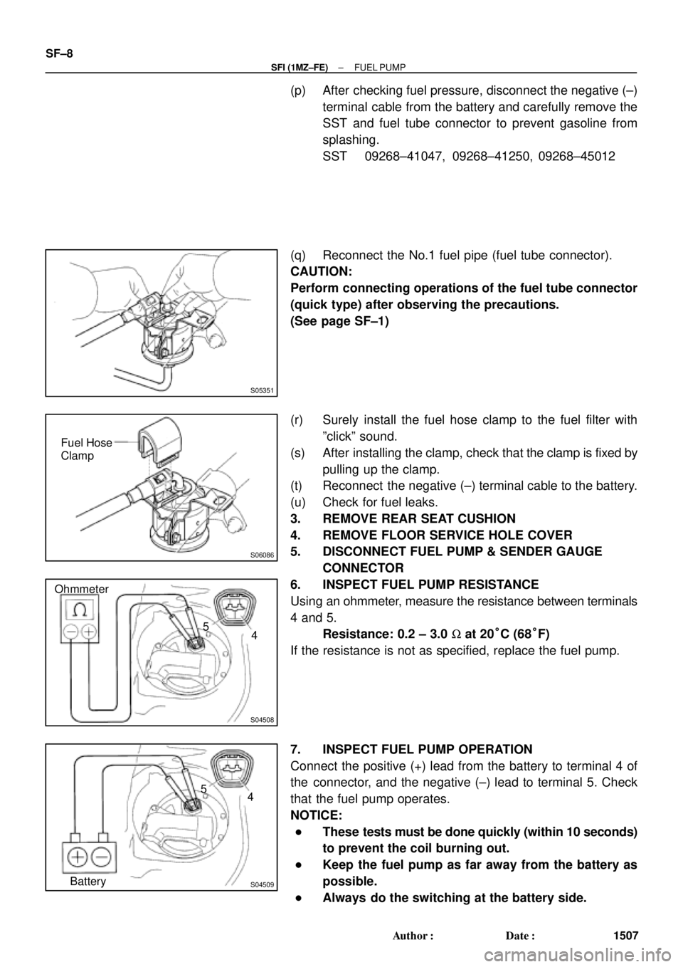
(r) Surely install the fuel hose clamp to the fuel filter with
ºclickº sound.
(s) After installing the clamp, check that the clamp is fixed by
pulling up the clamp.
(t) Reconnect the negative (±) terminal cable to the battery.
(u) Check for fuel leaks.
3. REMOVE REAR SEAT CUSHION
4. REMOVE FLOOR SERVICE HOLE COVER
5. DISCONNECT FUEL PUMP & SENDER GAUGE
CONNECTOR
6. INSPECT FUEL PUMP RESISTANCE
Using an ohmmeter, measure the resistance between terminals
4 and 5.
Resistance: 0.2 ± 3.0 W at 20°C (68°F)
If the resistance is not as specified, replace the fuel pump.
7. INSPECT FUEL PUMP OPERATION
Connect the positive (+) lead from the battery to terminal 4 of
the connector, and the negative (±) lead to terminal 5. Check
that the fuel pump operates.
NOTICE:
�These tests must be done quickly (within 10 seconds)
to prevent the coil burning out.
�Keep the fuel pump as far away from the battery as
possible.
�Always do the switching at the battery side.