Page 31 of 4770
3
CAMRY ± NEW FEATURES
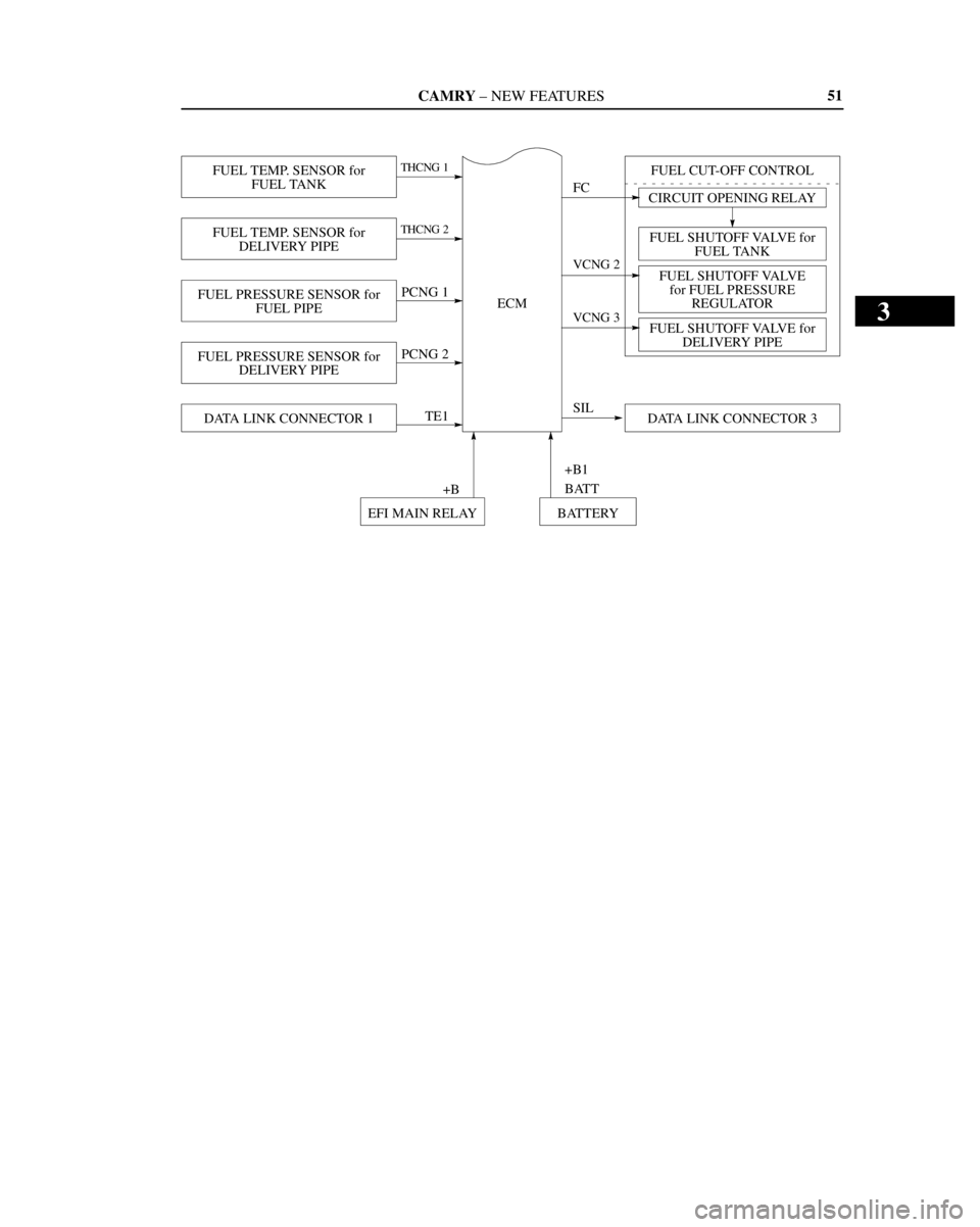
FUEL SHUTOFF VALVE for
FUEL TANK CIRCUIT OPENING RELAY
FUEL TEMP. SENSOR for
FUEL TANKTHCNG 1
FUEL TEMP. SENSOR for
DELIVERY PIPETHCNG 2
FUEL PRESSURE SENSOR for
FUEL PIPEPCNG 1
FUEL PRESSURE SENSOR for
DELIVERY PIPEPCNG 2
DATA LINK CONNECTOR 1TE1FUEL CUT-OFF CONTROL
FC
ECM
FUEL SHUTOFF VALVE
for FUEL PRESSURE
REGULATOR
FUEL SHUTOFF VALVE for
DELIVERY PIPE
DATA LINK CONNECTOR 3
EFI MAIN RELAY BATTERY+B
VCNG 2
VCNG 3
SIL
+B1
BATT
51
Page 138 of 4770
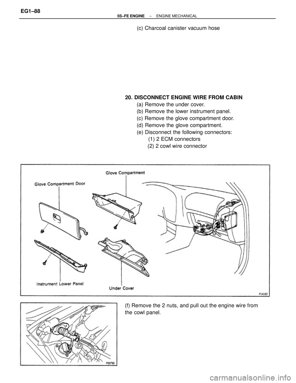
20. DISCONNECT ENGINE WIRE FROM CABIN
(a) Remove the under cover.
(b) Remove the lower instrument panel.
(c) Remove the glove compartment door.
(d) Remove the glove compartment.
(e) Disconnect the following connectors:
(1) 2 ECM connectors
(2) 2 cowl wire connector
(f) Remove the 2 nuts, and pull out the engine wire from
the cowl panel.(c) Charcoal canister vacuum hose
± 5S±FE ENGINEENGINE MECHANICALEG1±88
Page 180 of 4770
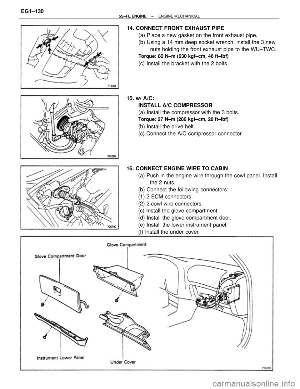
16. CONNECT ENGINE WIRE TO CABIN
(a) Push in the engine wire through the cowl panel. Install
the 2 nuts.
(b) Connect the following connectors:
(1) 2 ECM connectors
(2) 2 cowl wire connectors
(c) Install the glove compartment.
(d) Install the glove compartment door.
(e) Install the lower instrument panel.
(f) Install the under cover. 14. CONNECT FRONT EXHAUST PIPE
(a) Place a new gasket on the front exhaust pipe.
(b) Using a 14 mm deep socket wrench, install the 3 new
nuts holding the front exhaust pipe to the WU±TWC.
Torque: 82 N±m (630 kgf±cm, 46 ft±lbf)
(c) Install the bracket with the 2 bolts.
15. w/ A/C:
INSTALL A/C COMPRESSOR
(a) Install the compressor with the 3 bolts.
Torque: 27 N±m (280 kgf±cm, 20 ft±lbf)
(b) Install the drive belt.
(c) Connect the A/C compressor connector.
± 5S±FE ENGINEENGINE MECHANICALEG1±130
Page 223 of 4770
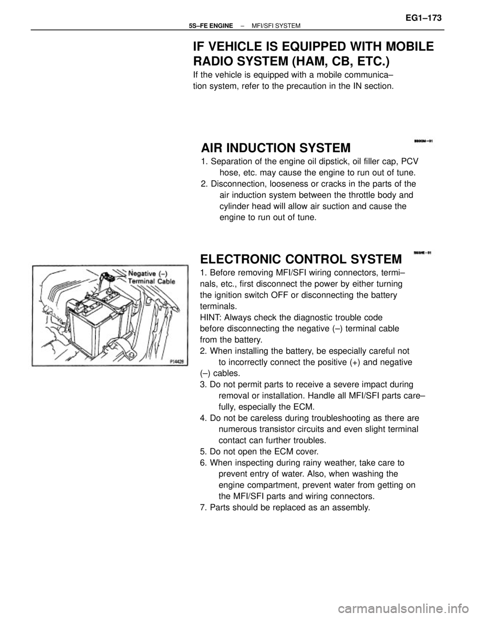
ELECTRONIC CONTROL SYSTEM
1. Before removing MFI/SFI wiring connectors, termi±
nals, etc., first disconnect the power by either turning
the ignition switch OFF or disconnecting the battery
terminals.
HINT: Always check the diagnostic trouble code
before disconnecting the negative (±) terminal cable
from the battery.
2. When installing the battery, be especially careful not
to incorrectly connect the positive (+) and negative
(±) cables.
3. Do not permit parts to receive a severe impact during
removal or installation. Handle all MFI/SFI parts care±
fully, especially the ECM.
4. Do not be careless during troubleshooting as there are
numerous transistor circuits and even slight terminal
contact can further troubles.
5. Do not open the ECM cover.
6. When inspecting during rainy weather, take care to
prevent entry of water. Also, when washing the
engine compartment, prevent water from getting on
the MFI/SFI parts and wiring connectors.
7. Parts should be replaced as an assembly.
AIR INDUCTION SYSTEM
1. Separation of the engine oil dipstick, oil filler cap, PCV
hose, etc. may cause the engine to run out of tune.
2. Disconnection, looseness or cracks in the parts of the
air induction system between the throttle body and
cylinder head will allow air suction and cause the
engine to run out of tune.
IF VEHICLE IS EQUIPPED WITH MOBILE
RADIO SYSTEM (HAM, CB, ETC.)
If the vehicle is equipped with a mobile communica±
tion system, refer to the precaution in the IN section.
± 5S±FE ENGINEMFI/SFI SYSTEMEG1±173
Page 239 of 4770
2. INSPECT INJECTOR RESISTANCE
(a) Disconnect the injector connector.
(b) Using an ohmmeter, measure the resistance between
the terminals.
Resistance:
Approx. 13.8�
If the resistance is not as specified, replace the injector.
(c) Reconnect the injector connector.
ON±VEHICLE INSPECTION
1. INSPECT INJECTOR OPERATION
Check operation sound from each injector.
(a) With the engine running or cranking, use a sound
scope to check that there is normal operating noise in
proportion to engine speed.
(b) If you have no sound scope, you can check the injec±
tor transmission operation with your finger.
If no sound or unusual sound is heard, check the
wiring connector, injector or injection signal from the
ECM.
INJECTOR
± 5S±FE ENGINEMFI/SFI SYSTEMEG1±189
Page 262 of 4770
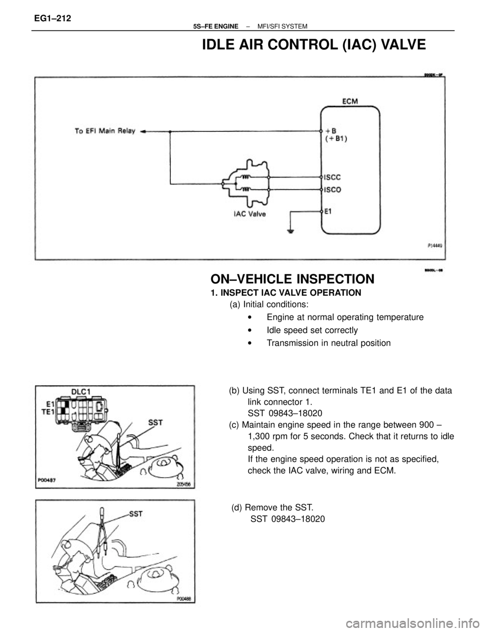
(b) Using SST, connect terminals TE1 and E1 of the data
link connector 1.
SST 09843±18020
(c) Maintain engine speed in the range between 900 ±
1,300 rpm for 5 seconds. Check that it returns to idle
speed.
If the engine speed operation is not as specified,
check the IAC valve, wiring and ECM.
ON±VEHICLE INSPECTION
1. INSPECT IAC VALVE OPERATION
(a) Initial conditions:
wEngine at normal operating temperature
wIdle speed set correctly
wTransmission in neutral position
IDLE AIR CONTROL (IAC) VALVE
(d) Remove the SST.
SST 09843±18020
± 5S±FE ENGINEMFI/SFI SYSTEMEG1±212
Page 281 of 4770
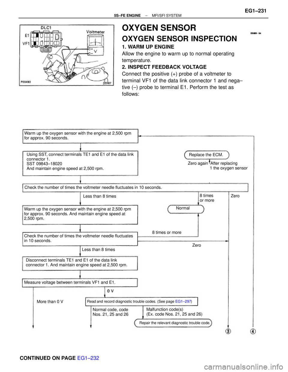
OXYGEN SENSOR
OXYGEN SENSOR INSPECTION
1. WARM UP ENGINE
Allow the engine to warm up to normal operating
temperature.
2. INSPECT FEEDBACK VOLTAGE
Connect the positive (+) probe of a voltmeter to
terminal VF1 of the data link connector 1 and nega±
tive (±) probe to terminal E1. Perform the test as
follows:
Using SST, connect terminals TE1 and E1 of the data link
connector 1.
SST 09843±18020
And maintain engine speed at 2,500 rpm.
Warm up the oxygen sensor with the engine at 2,500 rpm
for approx. 90 seconds. And maintain engine speed at
2,500 rpm.Warm up the oxygen sensor with the engine at 2,500 rpm
for approx. 90 seconds.
CONTINUED ON PAGE EG1±232
Disconnect terminals TE1 and E1 of the data link
connector 1. And maintain engine speed at 2,500 rpm. Check the number of times the voltmeter needle fluctuates
in 10 seconds.Zero again After replacing
1 the oxygen sensor
Check the number of times the voltmeter needle fluctuates in 10 seconds.
Read and record diagnostic trouble codes. (See page EG1±297)
Malfunction code(s)
(Ex. code Nos. 21, 25 and 26) Measure voltage between terminals VF1 and E1.
Repair the relevant diagnostic trouble code.
Normal code, code
Nos. 21, 25 and 26Replace the ECM.
Less than 8 timesLess than 8 times
8 times or more
More than 0 V8 times
or more
NormalZero
Zero
± 5S±FE ENGINEMFI/SFI SYSTEMEG1±231
Page 342 of 4770

HOW TO PROCEED WITH TROUBLESHOOTING
The Engine Control System broadly consists of the sensors, Engine Control Module (ECM) and actuators.
The ECM receives signals from various sensors, judges the operating conditions and determines the
optimum injection duration, timing, ignition timing and idle speed.
In general, the Engine Control System is considered to be a very intricate system to troubleshoot. But, the
fact is that if you proceed to inspect the circuit one by one following the procedures directed in this manu-
al, troubleshooting of this system is not complex.
This section explains the most ideal method of troubleshooting and tells how to carry out the necessary
repairs.
1. CUSTOMER PROBLEM ANALYSIS
Using the customer problem analysis check sheet for reference, ask the customer in as much details
as possible about the problem.
2. CHECK AND CLEAR DIAGNOSTIC TROUBLE CODE (PRECHECK)
Before confirming the problem symptom, first check the diagnostic trouble code and make a note of
any malfunction code which is output, then clear the code.
HINT: Output of the malfunction code indicates that there is a malfunction in the circuit indicated.
However, it does not indicate whether the malfunction is still occurring or occurred in the past and
returned to normal. In order to determine this, the problem sym toms should be confirmed in step 4
first and the diagnostic trouble code be rechecked in step [6].
Accordingly, if troubleshooting is begun based on the malfunction code only in diagnostic trouble
code check in step [2], it could result in a misdiagnosis, leading to troubleshooting of circuits which
are normal and making it more difficult to locate the cause of the problem.
3. SETTING THE TEST MODE DIAGNOSIS, [4] PROBLEM SYMPTOM CONFIRMATION,
[5] SYMPTOM SIMULATION
In order to find out the trouble more quickly, set the diagnosis check in test mode and with higher
sensing ability of the ECM, confirm the problem symptoms. If the trouble does not reappear, use the
symptom simulation method to make sure the trouble is reproduced.
6. DIAGNOSTIC TROUBLE CODE CHECK IN TEST MODE
Check the diagnostic trouble code in test mode. If the malfunction code is output, proceed to step. If the
normal code is output, proceed to step [7].
7. BASIC INSPECTION
Carry out basic inspection such as the spark check and fuel pressure check, etc.
8. DIAGNOSTIC TROUBLE CODE CHART
If the malfunction code is displayed, proceed to inspect the circuit indicated by the chart for each
code.
9. MATRIX CHART OF PROBLEM SYMPTOMS
If the normal code is displayed in the diagnosis in test mode, perform troubleshooting according to
the inspection order in the Matrix Chart of Problem Symptoms.
10. PARTS INSPECTION
When the Matrix Chart of Problem Symptoms instructs to check the parts, proceed to parts inspection
section included in this manual.
11. CIRCUIT INSPECTION
Determine if the malfunction is the sensor, actuator, wire harness, connector or the ECM.
± 5S±FE ENGINEHOW TO PROCEED WITH TROUBLESHOOTINGEG1±292