Page 301 of 4770
2. INSPECT COOLING SYSTEM FOR LEAKS
(a) Fill the radiator with coolant and attach a radiator cap
tester.
(b) Warm up the engine.
(c) Pump it to 118 kPa (1.2 kgf/cm�, 17.1 psi), and check
that the pressure does not drop.
If the pressure drops, check the hoses, radiator or
water pump for leaks. If no external leaks are found,
check the heater core, cylinder block and head.
RADIATOR REMOVAL
1. DISCONNECT NEGATIVE (±) TERMINAL CABLE
FROM BATTERY
CAUTION: Work must be started after 90 seconds from
the time the ignition switch is turned to the ªLOCKº
position and the negative (±) terminal cable is discon±
nected from the battery.
COMPONENTS FOR REMOVAL AND
INSTALLATION
± 5S±FE ENGINECOOLING SYSTEMEG1±251
Page 576 of 4770

101 BODY ELECTRICALÐAIR CONDITIONING
AIR CONDITIONING
� DESCRIPTION
1. General
The air conditioning system in the new Camry has the following features:
�The rotary switch and lever type heater control panel is used.
�As in the previous model, an air conditioning unit that incorporates a blower, heater and cooler unit, has been
adopted.
�The duct size of the blower unit has been enlarged.
�An aluminum heater core has been adopted on all models.
�The defroster nozzle inner wall is modified into a radial configuration for smoother air flow.
�A defroster±linked air conditioning start up control, which automatically engages the air conditioning when the
defroster mode has been selected, is provided.
�The air conditioning amplifier which is integrated with the ECM has been adopted on the 5S±FE engine model.
�Performance�
Model
NewPreviousItemNewPrevious
Heat Output W (Kcal/H)5580 (4800)u
HeaterAir Flow Volume* m3/h360u
Power Consumption W220u
Ai
Heat Output W (Kcal/H)5300 (4560)5350 (4600)
Air
ConditionerAir Flow Volume m3/h520530Conditioner
Power Consumption W260u
DefrosterAir Flow Volume* m3/h360u
*: With side vent closed.
�Specifications�
Model
NewPreviousItemNewPrevious
aterTypeDimpled Tube Typeu
and Hea
t
Heater CoreSize WxHxL mm (in.)160 x 220 x 32
(6.3 x 8.7 x 1.3)u
ion a
n
Fin Pitch mm (in.)1.8 (0.07)u
ntilati
o
Blower
Motor TypeA80Fs13TS80Fs12.5T
Ve n
tBlowerFan Size Dia. xH mm (in.)150 x 75 (5.9 x 3.0)u
Type3 Passage Flow Typeu
g
CondenserSize WxHxL mm (in.)415.6 x 726 x 22
(16.4 x 28.6 x 0.9)435.2 x 686 x 22
(17.1 x 27.0 x 0.9)
ingFin Pitch mm (in.)4.5 (0.18)3.5 (0.14)
ioni
n
TypeDrawn Cup Typeu
onditi
o
EvaporatorSize WxHxL mm (in.)260 x 252 x 90
(10.2 x 9.9 x 3.5)u
r C
oFin Pitch mm (in.)4.0 (0.16)u
Air CompressorType10PA17CuARefrigerandTypeHFC134a (R134a)u
Page 1028 of 4770

5
CAMRY ± OUTLINE OF NEW FEATURES
160CM05
27
8. Lighting
Daytime running light system with automatic light control sensor is provided on the models for U.S.A. as
optional equipment, and as standard equipment on the models for Canada.
The basic construction and operation are the same as in the '99 Camry Solara.
9. Air Conditioning
�An aluminum heater core has been adopted on all models.
�A quick joint has been adopted for joining the air conditioner tube.
10.SRS Airbag
A 3-sensor type airbag system has been adopted with the addition of a front airbag sensors, which senses the
impact of a frontal collision. For details, see the General 1999 Features section.
11. Power Seat
A power seat is available as an option for the driver seat on the LE grade model. Also, a power seat is available
as an option for the driver and front passenger seats on the LE grade model with leather seat.
12. Audio
�An AM / FM ETR with Cassette Deck and CD Player with built-in power amplifier is available as an option
on the LE grade model.
�The pole antenna, which was provided on the CE grade model, has been changed to the rear window im-
printed antenna.
13. Cruise Control System
The cruise control ECU has been made more compact.
Page 2363 of 4770
RADIATOR
CO±15
1589 Author�: Date�:
ON±VEHICLE INSPECTION
1. REMOVE RADIATOR CAP
CAUTION:")
CO06H±04
Z00570
30° or More
Radiator CapRadiator Cap Tester
B06362
Radiator Cap Tester
± COOLING (5S±FE)RADIATOR
CO±15
1589 Author�: Date�:
ON±VEHICLE INSPECTION
1. REMOVE RADIATOR CAP
CAUTION:
To avoid the danger of being burned, do not remove the ra-
diator cap while the engine and radiator are still hot, as fluid
and steam can be blown out under pressure.
2. INSPECT RADIATOR CAP
NOTICE:
�If the radiator cap has contaminations, always rinse
it with water.
�Before using a radiator cap tester, wet the relief valve
and pressure valve with engine coolant or water.
�When performing steps (a) and (b) below, keep the
tester at an angle of over 30° above the horizontal.
(a) Using a radiator cap tester, slowly pump the tester and
check that air is coming from the vacuum valve.
Pump speed: 1 push/(3 seconds or more)
NOTICE:
Push the pump at a constant speed.
If air is not coming from the vacuum valve, replace the radiator
cap.
(b) Pump the tester, and measure the relief valve opening
pressure.
Pump speed: 1 push within 1 second
NOTICE:
This pump speed is for the first pump only (in order to close
the vacuum valve). After this, the pump speed can be re-
duced.
Standard opening pressure:
74 ± 103 kPa (0.75 ± 1.05 kgf/cm
2, 10.7 ± 14.9 psi)
Minimum opening pressure:
59 kPa (0.6 kgf/cm
2, 8.5 psi)
HINT:
Use the tester's maximum reading as the opening pressure.
If the opening pressure is less than minimum, replace the radia-
tor cap.
3. INSPECT COOLING SYSTEM FOR LEAKS
(a) Fill the radiator with coolant, and attach a radiator cap tes-
ter.
(b) Warm up the engine.
(c) Pump it to 118 kPa (1.2 kgf/cm
2, 17.1 psi), and check that
the pressure does not drop.
If the pressure drops, check the hoses, radiator or water pump
for leaks. If no external leaks are found, check the heater core,
cylinder block and head.
4. REINSTALL RADIATOR CAP
Page 2397 of 4770
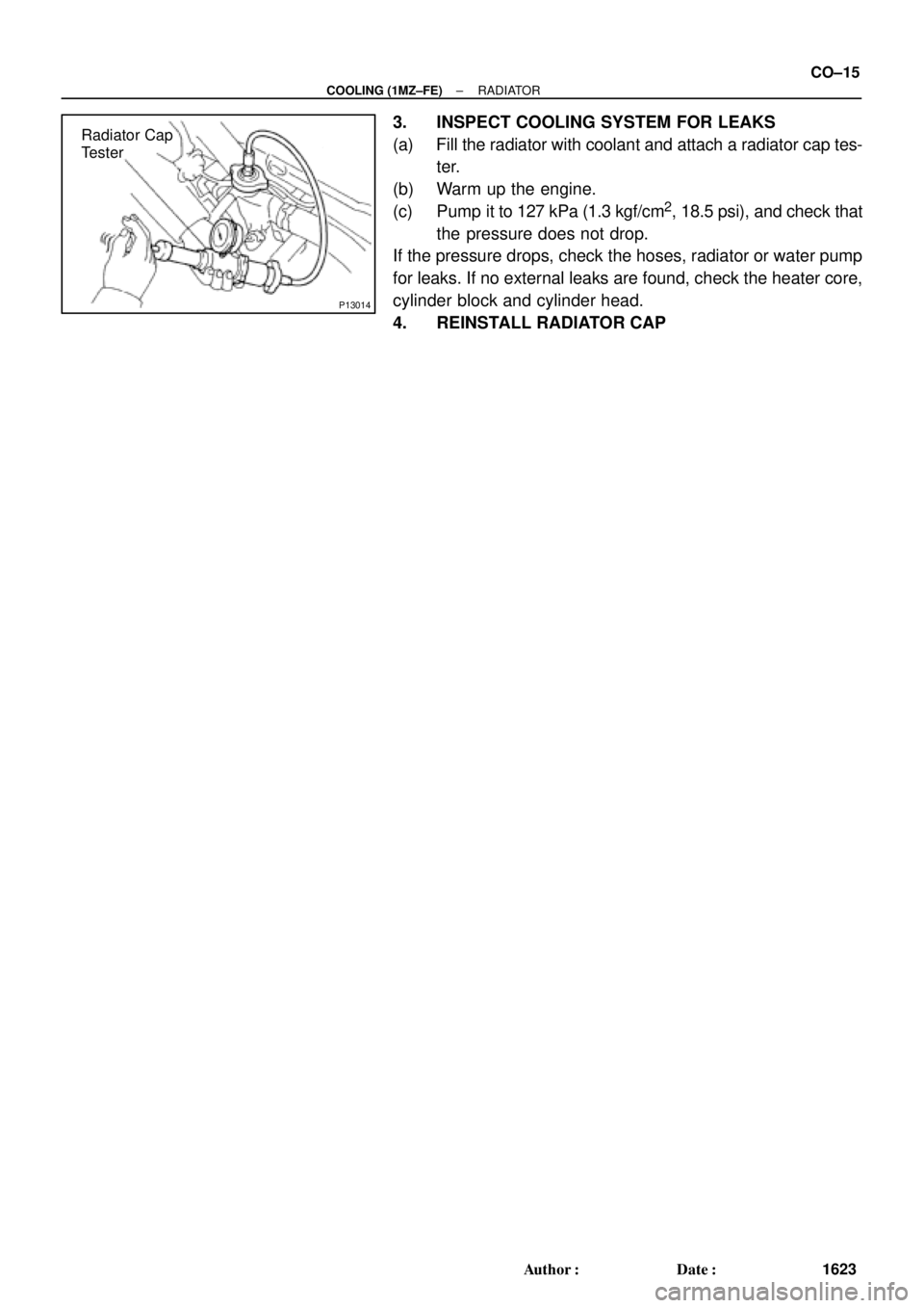
P13014
Radiator Cap
Tester
± COOLING (1MZ±FE)RADIATOR
CO±15
1623 Author�: Date�:
3. INSPECT COOLING SYSTEM FOR LEAKS
(a) Fill the radiator with coolant and attach a radiator cap tes-
ter.
(b) Warm up the engine.
(c) Pump it to 127 kPa (1.3 kgf/cm
2, 18.5 psi), and check that
the pressure does not drop.
If the pressure drops, check the hoses, radiator or water pump
for leaks. If no external leaks are found, check the heater core,
cylinder block and cylinder head.
4. REINSTALL RADIATOR CAP