Page 56 of 4770
Plug for vacuum hose, fuel hose
etc.
Battery specific gravity gauge09256±00030 Hose Plug Set
09904±00010 Expander Set
Piston ring compressorEngine tune±up tester Connecting rod aligner
Precision straight edge
EQUIPMENT
Piston ring expander Compression gauge
Magnetic finger Cylinder gauge
Torque wrenchDye penetrant CO/HC meterCaliper gauge
Spring tester
ThermometerDial indicator
Steel squareMicrometer
Valve spring
Valve spring Plastigage
Soft brushHeater
± 5S±FE ENGINEENGINE MECHANICALEG1±6
Page 195 of 4770
Reduces blow±by gas (HC)
Reduces evaporative HC
Reduces NOx
Reduces C0, HC and NOx
Regulates all engine conditions for reduction
of exhaust emissions. Positive crankcase ventilation
Fuel evaporative emission control
Exhaust gas recirculation
Three±way catalytic converter
*Multiport fuel injection/Sequential
multiport fuel injection
PREPARATION
SST (SPECIAL SERVICE TOOLS)
EMISSION CONTROL SYSTEMS
º For inspection and repair of the MFI/SFI system, refer to MFI/SFI Section.
SSM (SPECIAL SERVICE MATERIALS)
08833±00070 Adhesive 1311,
THREE BOND 1311 or equivalent
RECOMMENDED TOOLS
SYSTEM PURPOSE
09082±00050 TOYOTA Electrical Tester SetPCV
EVAP
EG R
TWC
MFI/SFI
09843±18020 Diagnosis Check Wire
EQUIPMENT
Torque wrench
Vacuum gaugeAbbreviation
Thermometer
Tachometer
Purpose
system
Heater
¿¿VTVV
TVV
± 5S±FE ENGINEEMISSION CONTROL SYSTEMSEG1±145
Page 220 of 4770
PREPARATION
SST (SPECIAL SERVICE TOOLS)
(90405±09015) No.1 Union (09268±41090) No.7 union (09268±41080) No.6 union
09631±22020 Power Steering Hose Nut
14 x 17 mm Wrench Set
RECOMMENDED TOOLS
Plug for vacuum hose, fuel hose
etc. 09268±41045 Injection Measuring Tool Set
09082±00050 TOYOTA Electrical Tester Set 09842±30070 Wiring ªFº EFI Inspection 09268±45012 EFI Fuel Pressure Gauge
09843±18020 Diagnosis Check Wire
09200±00010 Engine Adjust Kit
09258±00030 Hose Plug SetFuel line flare nut
± 5S±FE ENGINEMFI/SFI SYSTEMEG1±170
Page 222 of 4770

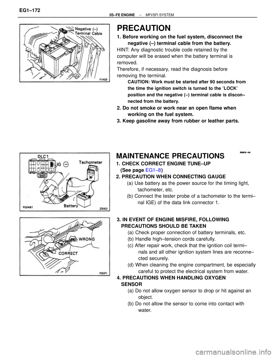
PRECAUTION
1. Before working on the fuel system, disconnect the
negative (±) terminal cable from the battery.
HINT: Any diagnostic trouble code retained by the
computer will be erased when the battery terminal is
removed.
Therefore, if necessary, read the diagnosis before
removing the terminal.
CAUTION: Work must be started after 90 seconds from
the time the ignition switch is turned to the 'LOCK'
position and the negative (±) terminal cable is discon±
nected from the battery.
2. Do not smoke or work near an open flame when
working on the fuel system.
3. Keep gasoline away from rubber or leather parts.
3. IN EVENT OF ENGINE MISFIRE, FOLLOWING
PRECAUTIONS SHOULD BE TAKEN
(a) Check proper connection of battery terminals, etc.
(b) Handle high±tension cords carefully.
(c) After repair work, check that the ignition coil termi±
nals and all other ignition system lines are reconne±
cted securely.
(d) When cleaning the engine compartment, be especially
careful to protect the electrical system from water.
4. PRECAUTIONS WHEN HANDLING OXYGEN
SENSOR
(a) Do not allow oxygen sensor to drop or hit against an
object.
(b) Do not allow the sensor to come into contact with
water.
MAINTENANCE PRECAUTIONS
1. CHECK CORRECT ENGINE TUNE±UP
(See page EG1±8)
2. PRECAUTION WHEN CONNECTING GAUGE
(a) Use battery as the power source for the timing light,
tachometer, etc.
(b) Connect the tester probe of a tachometer to the termi±
nal IGE) of the data link connector 1.
± 5S±FE ENGINEMFI/SFI SYSTEMEG1±172
Page 231 of 4770

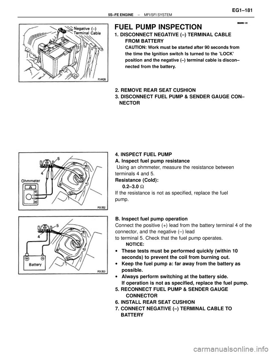
B. Inspect fuel pump operation
Connect the positive (+) lead from the battery terminal 4 of the
connector, and the negative (±) lead
to terminal 5. Check that the fuel pump operates.
NOTICE:
wThese tests must be performed quickly (within 10
seconds) to prevent the coil from burning out.
wKeep the fuel pump a: far away from the battery as
possible.
wAlways perform switching at the battery side.
If operation is not as specified, replace the fuel pump.
5. RECONNECT FUEL PUMP & SENDER GAUGE
CONNECTOR
6. INSTALL REAR SEAT CUSHION
7. CONNECT NEGATIVE (±) TERMINAL CABLE TO
BATTERY
FUEL PUMP INSPECTION
1. DISCONNECT NEGATIVE (±) TERMINAL CABLE
FROM BATTERY
CAUTION: Work must be started after 90 seconds from
the time the Ignition switch Is turned to the 'LOCK'
position and the negative (±) terminal cable is discon±
nected from the battery.
4. INSPECT FUEL PUMP
A. Inspect fuel pump resistance
Using an ohmmeter, measure the resistance between
terminals 4 and 5.
Resistance (Cold):
0.2±3.0 W
If the resistance is not as specified, replace the fuel
pump. 2. REMOVE REAR SEAT CUSHION
3. DISCONNECT FUEL PUMP & SENDER GAUGE CON±
NECTOR
± 5S±FE ENGINEMFI/SFI SYSTEMEG1±181
Page 245 of 4770
(c) Install a new O±ring to the fuel inlet of pressure
regulator.
(d) Connect SST (hose) to the fuel inlet of the pressure
regulator with SST (union) and the 2 bolts.
SST 09268±41045 (09268±41090)
Torque: 5.4 N±m (55 kgf±cm, 48 ft±lbf)
(e) Connect the fuel return hose to the fuel outlet of the
pressure regulator with SST (union), 2 new gaskets
and union bolts. (a) Disconnect the fuel hose from the fuel filter outlet.
(b) Connect SST (union and hose) to the fuel filter outlet
with 2 new gaskets and union bolts.
SST 09268±41045 (90405±09015)
Torque: 29 N±m (300 kgf±cm, 22 ft±lbf)
HINT: Use the vehicle's fuel filter.
INJECTORS INSPECTION
1. INSPECT INJECTOR INJECTION
CAUTION: Keep injector clear of sparks during the test.
(f) California:
Remove the 2 O±rings, insulator and grommet from
each injector.
(g) Except California:
Remove the O±ring and grommet from each injector.
± 5S±FE ENGINEMFI/SFI SYSTEMEG1±195
Page 246 of 4770

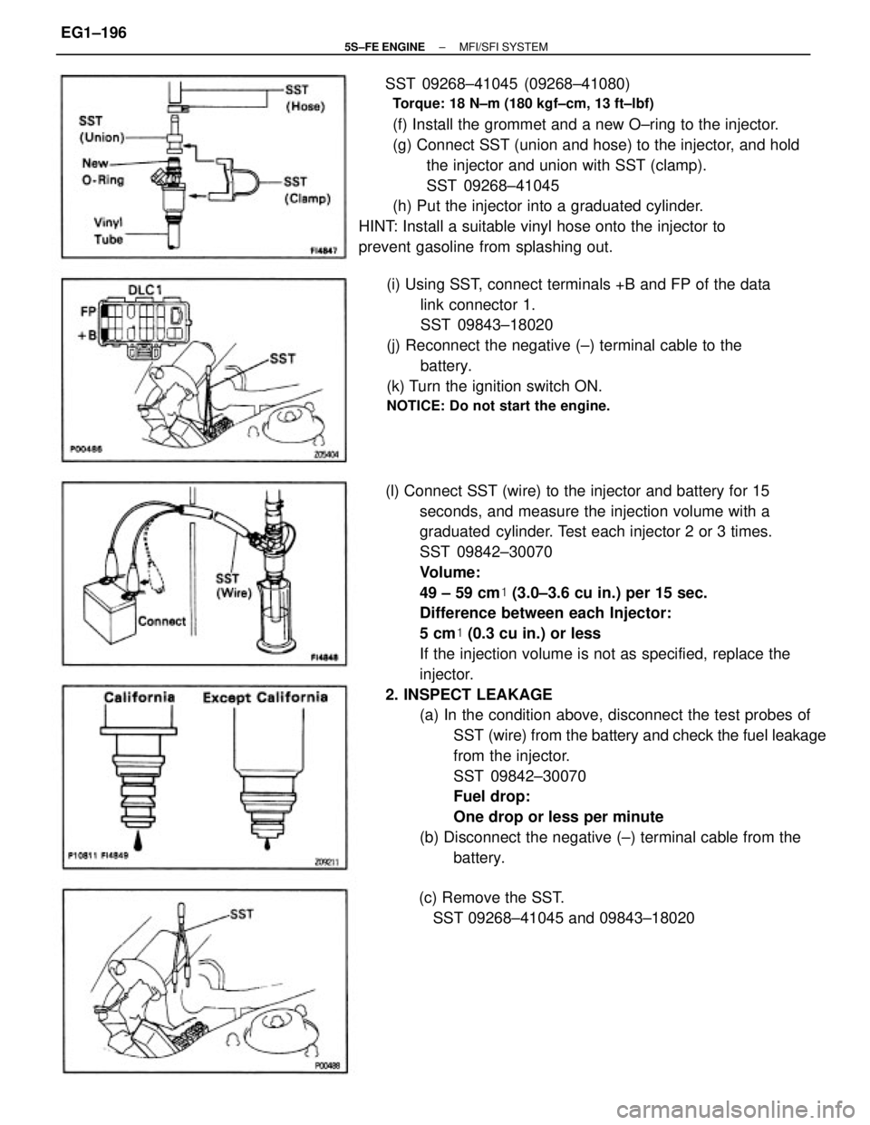
(l) Connect SST (wire) to the injector and battery for 15
seconds, and measure the injection volume with a
graduated cylinder. Test each injector 2 or 3 times.
SST 09842±30070
Volume:
49 ± 59 cm� (3.0±3.6 cu in.) per 15 sec.
Difference between each Injector:
5 cm� (0.3 cu in.) or less
If the injection volume is not as specified, replace the
injector.
2. INSPECT LEAKAGE
(a) In the condition above, disconnect the test probes of
SST (wire) from the battery and check the fuel leakage
from the injector.
SST 09842±30070
Fuel drop:
One drop or less per minute
(b) Disconnect the negative (±) terminal cable from the
battery. SST 09268±41045 (09268±41080)
Torque: 18 N±m (180 kgf±cm, 13 ft±lbf)
(f) Install the grommet and a new O±ring to the injector.
(g) Connect SST (union and hose) to the injector, and hold
the injector and union with SST (clamp).
SST 09268±41045
(h) Put the injector into a graduated cylinder.
HINT: Install a suitable vinyl hose onto the injector to
prevent gasoline from splashing out.
(i) Using SST, connect terminals +B and FP of the data
link connector 1.
SST 09843±18020
(j) Reconnect the negative (±) terminal cable to the
battery.
(k) Turn the ignition switch ON.
NOTICE: Do not start the engine.
(c) Remove the SST.
SST 09268±41045 and 09843±18020
± 5S±FE ENGINEMFI/SFI SYSTEMEG1±196
Page 285 of 4770
2. CONNECT TACHOMETER TO ENGINE
Connect the test probe of a tachometer to terminal IG
(±) of the data link connector 1.
NOTICE:
wNEVER allow the tachometer terminal to touch
ground as it could result in damage to the igniter
and/or ignition coil.
wAs some tachometers are not compatible with this
ignition system, we recommend that you confirm
the compatibility of yours before use.
3. INSPECT FUEL CUT RPM
(a) Increase the engine speed to at least 2,500 rpm.
(b) Use a sound scope to check for injector operating
noise.
(c) Check that when the throttle lever is released, injector
operation noise stops momentarily and then resumes.
HINT: Measure with the A/C OFF.
Fuel return speed:
1,500 rpm
4. DISCONNECT TACHOMETER
FUEL CUT RPM
FUEL CUT RPM INSPECTION
1. WARM UP ENGINE
Allow the engine to warm up to normal operating
temperature.
± 5S±FE ENGINEMFI/SFI SYSTEMEG1±235