Page 70 of 4770

IDLE SPEED INSPECTION
1. INITIAL CONDITIONS
(a) Engine at normal operating temperature
(b) Air cleaner installed
(c) All pipes and hoses of air induction system connected
(d) All vacuum lines properly connected
(e) MFI/SFI system wiring connectors fully plugged
(f) All operating accessories switched OFF
(g) Ignition timing set correctly
(h) Transmission in neutral position
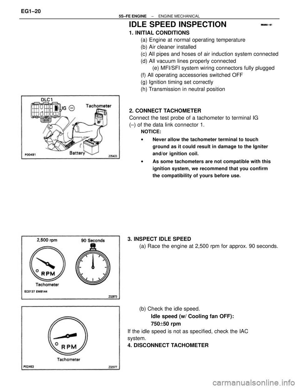
2. CONNECT TACHOMETER
Connect the test probe of a tachometer to terminal IG
(±) of the data link connector 1.
NOTICE:
wNever allow the tachometer terminal to touch
ground as it could result in damage to the Igniter
and/or ignition coil.
wAs some tachometers are not compatible with this
ignition system, we recommend that you confirm
the compatibility of yours before use.
(b) Check the idle speed.
Idle speed (w/ Cooling fan OFF):
750+50 rpm
If the idle speed is not as specified, check the IAC
system.
4. DISCONNECT TACHOMETER 3. INSPECT IDLE SPEED
(a) Race the engine at 2,500 rpm for approx. 90 seconds.
± 5S±FE ENGINEENGINE MECHANICALEG1±20
Page 71 of 4770

IDLE AND OR 2,500 RPM CO/HC
CHECK
HINT: This check is used only to determine whether or
not the idle CO/HC complies with regulations.
1. INITIAL CONDITIONS
(a) Engine at normal operating temperature
(b) Air cleaner installed
(c) All pipes and hoses of air induction system connected
(d) All accessories switched OFF
(e) All vacuum lines properly connected
HINT: All vacuum hoses for EGR systems, etc. should
be properly connected.
(f) MFI/SFI system wiring connectors fully plugged
(g) Ignition timing set correctly
(h) Transmission in neutral position
(i) Tachometer and CO/HC meter calibrated by hand.
4. INSERT CO/HC METER TESTING PROBE AT LEAST
40 cm (1.3 ft) INTO TAILPIPE DURING IDLING
5. IMMEDIATTELY CHECK CO/HC CONCENTRATION
AT IDLE AND/OR 2,500 RPM
Complete the measuring within 3 minutes.
HINT: When performing the 2 mode (2,500 rpm and
idle) test, follow the measurement order prescribed by
the applicable local regulations. 2. START ENGINE
3. RACE ENGINE AT 2,500 RPM FOR APPROX. 180
SECONDS
± 5S±FE ENGINEENGINE MECHANICALEG1±21
Page 140 of 4770
30. REMOVE ENGINE AND TRANSAXLE ASSEMBLY
FROM VEHICLE
(a) Lift the engine out of the vehicle slowly and carefully.
NOTICE: Be careful not to hit the PS gear housing or
perk/neutral position switch (A/T).
(b) Make sure the engine is clear of all wiring, hoses and
cables.
(c) Place the engine and transaxle assembly onto the
stand. 26. DISCONNECT RR ENGINE MOUNTING INSULATOR
(a) Remove the hole plugs.
(b) Remove the 3 nuts, and disconnect the mounting
insulator.
27. DISCONNECT FR ENGINE MOUNTING INSULATOR
Remove the 3 bolts, and disconnect the mounting
insulator.
28. ATTACH ENGINE SLING DEVICE TO ENGINE
HANGERS
29. REMOVE ENGINE MOVING CONTROL ROD
Remove the 3 bolts and control rod.
± 5S±FE ENGINEENGINE MECHANICALEG1±90
Page 220 of 4770
PREPARATION
SST (SPECIAL SERVICE TOOLS)
(90405±09015) No.1 Union (09268±41090) No.7 union (09268±41080) No.6 union
09631±22020 Power Steering Hose Nut
14 x 17 mm Wrench Set
RECOMMENDED TOOLS
Plug for vacuum hose, fuel hose
etc. 09268±41045 Injection Measuring Tool Set
09082±00050 TOYOTA Electrical Tester Set 09842±30070 Wiring ªFº EFI Inspection 09268±45012 EFI Fuel Pressure Gauge
09843±18020 Diagnosis Check Wire
09200±00010 Engine Adjust Kit
09258±00030 Hose Plug SetFuel line flare nut
± 5S±FE ENGINEMFI/SFI SYSTEMEG1±170
Page 223 of 4770

ELECTRONIC CONTROL SYSTEM
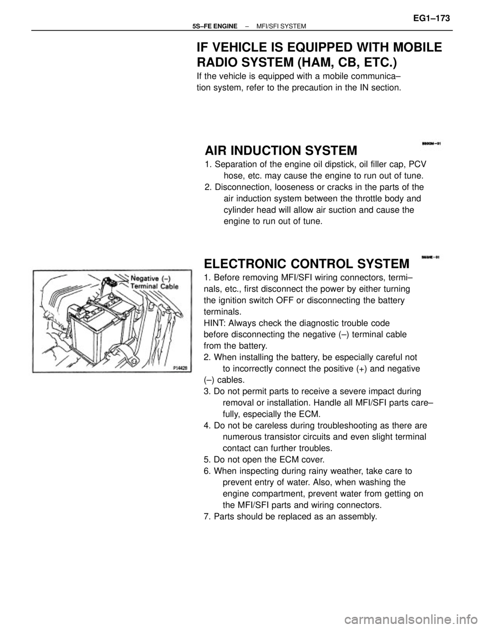
1. Before removing MFI/SFI wiring connectors, termi±
nals, etc., first disconnect the power by either turning
the ignition switch OFF or disconnecting the battery
terminals.
HINT: Always check the diagnostic trouble code
before disconnecting the negative (±) terminal cable
from the battery.
2. When installing the battery, be especially careful not
to incorrectly connect the positive (+) and negative
(±) cables.
3. Do not permit parts to receive a severe impact during
removal or installation. Handle all MFI/SFI parts care±
fully, especially the ECM.
4. Do not be careless during troubleshooting as there are
numerous transistor circuits and even slight terminal
contact can further troubles.
5. Do not open the ECM cover.
6. When inspecting during rainy weather, take care to
prevent entry of water. Also, when washing the
engine compartment, prevent water from getting on
the MFI/SFI parts and wiring connectors.
7. Parts should be replaced as an assembly.
AIR INDUCTION SYSTEM
1. Separation of the engine oil dipstick, oil filler cap, PCV
hose, etc. may cause the engine to run out of tune.
2. Disconnection, looseness or cracks in the parts of the
air induction system between the throttle body and
cylinder head will allow air suction and cause the
engine to run out of tune.
IF VEHICLE IS EQUIPPED WITH MOBILE
RADIO SYSTEM (HAM, CB, ETC.)
If the vehicle is equipped with a mobile communica±
tion system, refer to the precaution in the IN section.
± 5S±FE ENGINEMFI/SFI SYSTEMEG1±173
Page 224 of 4770
(b) Insert the test probe into the connector from wiring
side when checking the continuity, amperage or volt±
age.
(c) Do not apply unnecessary force to the terminal.
(d) After checking, install the water±proofing rubber on
the connector securely. 8. Care is required when pulling out and inserting wiring
connectors.
(a) Release the lock and pull out the connector, pulling on
the connectors.
9. When inspecting a connector with a volt/ohmmeter.
(a) Carefully take out the water±proofing rubber if it is a
water±proof type connector.
10. Use SST for inspection or test of the injector or its
wiring connector.
SST 09842±30070 (b) Fully insert the connector and check that it is locked.
± 5S±FE ENGINEMFI/SFI SYSTEMEG1±174
Page 228 of 4770
2. CHECK FUEL PRESSURE
(a) Check that the battery voltages is above 12 volts.
(b) Disconnect the negative (±) terminal cable from the
battery.
CAUTION: Work must be started after 90 seconds from
the time the ignition switch is turned to the ªLOCKº
position and the negative (±) terminal cable is discon±
nected from the battery.
If there is no pressure, check the following parts:
wFusible link
wFuses (AM2 30A, EFI 15A, IGN 7.5A)
wEFI main relay
wFuel pump
wWiring connections (c) Check that there is pressure in the hose from the fuel
filter.
HINT: At this time, you will hear fuel return noise.
(e) Remove the SST.
SST 09843±18020 (d) Turn the ignition switch OFF.
± 5S±FE ENGINEMFI/SFI SYSTEMEG1±178
Page 239 of 4770
2. INSPECT INJECTOR RESISTANCE
(a) Disconnect the injector connector.
(b) Using an ohmmeter, measure the resistance between
the terminals.
Resistance:
Approx. 13.8�
If the resistance is not as specified, replace the injector.
(c) Reconnect the injector connector.
ON±VEHICLE INSPECTION
1. INSPECT INJECTOR OPERATION
Check operation sound from each injector.
(a) With the engine running or cranking, use a sound
scope to check that there is normal operating noise in
proportion to engine speed.
(b) If you have no sound scope, you can check the injec±
tor transmission operation with your finger.
If no sound or unusual sound is heard, check the
wiring connector, injector or injection signal from the
ECM.
INJECTOR
± 5S±FE ENGINEMFI/SFI SYSTEMEG1±189