Page 2453 of 4770

DI±33
268 Author�: Date�:
DTC P0106 Manifold Absolute Pressure Circuit
Range/Performance Problem
CIRCUIT DESCRIPTION
Refer to DTC P0105 (Manifold Absolute Pressure/Barom")
± DIAGNOSTICSENGINE (5S±FE)
DI±33
268 Author�: Date�:
DTC P0106 Manifold Absolute Pressure Circuit
Range/Performance Problem
CIRCUIT DESCRIPTION
Refer to DTC P0105 (Manifold Absolute Pressure/Barometric Pressure Circuit Malfunction) on page
DI±29.
DTC No.DTC Detecting ConditionTrouble Area
P0106
After engine is warmed up, conditions (a) and (b) continue with
engine speed 400 ~ 1,000 rpm
(2 trip detection logic)
(a) Throttle valve fully closed
(b) Manifold absolute pressure sensor output > 3.0 V
�Manifold absolute pressure sensorP0106Condition (c) and (d) continue with engine speed 2,500 rpm or
less
(2 trip detection logic)
(c) VTA > 1.85
(d) Manifold absolute pressure sensor output < 1.0 V
�Manifold absolute ressure sensor
�Vacuum line
WIRING DIAGRAM
Refer to DTC P0105 (Manifold Absolute Pressure/Barometric Pressure Circuit Malfunction) on page
DI±29.
INSPECTION PROCEDURE
HINT:
�If DTC P0105 (Manifold Absolute Pressure/Barometric Pressure Circuit Malfunction) and P0106 (Man-
ifold Absolute Pressure /Barometric Pressure Circuit Range/Performance Problem) are output simul-
taneously, manifold absolute pressure sensor circuit may be open. Perform troubleshooting of DTC
P0105 first.
�If DTC P0105 (Manifold Absolute Pressure/Barometric Pressure Circuit Malfunction), P0106 (Manifold
Absolute Pressure /Barometric Pressure Circuit Range/Performance Problem), P0110 (Intake Air
Temp. Circuit Malfunction), P0115 (Engine Coolant Temp. Circuit Malfunction) and P0120 (Throttle/
Pedal Position Sensor/Switch ºAº Circuit Malfunction) are output simultaneously, E2 (sensor ground)
may be open.
�Read freeze frame data using TOYOTA hand±held tester or OBD II scan tool. Because freeze frame
records the engine conditions when the malfunction is detected, when troubleshooting it is useful for
determining whether the vehicle was running or stopped, the engine warmed up or not, the air±fuel
ratio lean or rich, etc. at the time of the malfunction.
1 Are there any other codes (besides DTC P0106) being output?
YES Go to relevant DTC chart.
NO
DI00N±04
Page 2455 of 4770

Acceptable
Resistance kW
± 20 0 20 40 60 80 100
(± 4) (32) (68) (104) (140) (176) (212) 30
20
10
5
3
2
1
0.5
0.3
0.2
0.1
Te m p .°C (F°)
± DIAGNOSTICSENGINE (5S±FE)
DI±35
270 Aut")
FI4741
(fig.1)
Acceptable
Resistance kW
± 20 0 20 40 60 80 100
(± 4) (32) (68) (104) (140) (176) (212) 30
20
10
5
3
2
1
0.5
0.3
0.2
0.1
Te m p .°C (F°)
± DIAGNOSTICSENGINE (5S±FE)
DI±35
270 Author�: Date�:
DTC P0110 Intake Air Temp. Circuit Malfunction
CIRCUIT DESCRIPTION
The intake air temp. sensor is built into the air cleaner cap and
senses the intake air temperature.
A thermistor built in the sensor changes the resistance value
according to the intake air temperature, the lower the intake air
temperature, the greater the thermistor resistance value, and
the higher the intake air temperature, the lower the thermistor
resistance value (See fig.1).
The air intake temperature sensor is connected to the ECM
(See below). The 5 V power source voltage in the ECM is ap-
plied to the intake air temp. sensor from the terminal THA via
a resistor R.
That is, the resistor R and the intake air temp. sensor are con-
nected in series. When the resistance value of the intake air
temp. sensor changes in accordance with changes in the intake
air temperature, the potential at terminal THA also changes.
Based on this signal, the ECM increases the fuel injection vol-
ume to improve driveability during cold engine operation.
If the ECM detects the DTC P0110, it operates the fail safe func-
tion in which the intake air temperature is assumed to be 20°C
(68°F).
DTC No.DTC Detecting ConditionTrouble Area
P0110Open or short in intake air temp. sensor circuit
�Open or short in intake air temp. sensor circuit
�Intake air temp. sensor
�ECM
HINT:
After confirming DTC P0110, use the OBD II scan tool or TOYOTA hand±held tester to confirm the intake
air temperature from the CURRENT DATA.
Temperature DisplayedMalfunction
±40°C (±40°F)Open circuit
140°C (284°F) or moreShort circuit
DI00O±05
Page 2456 of 4770
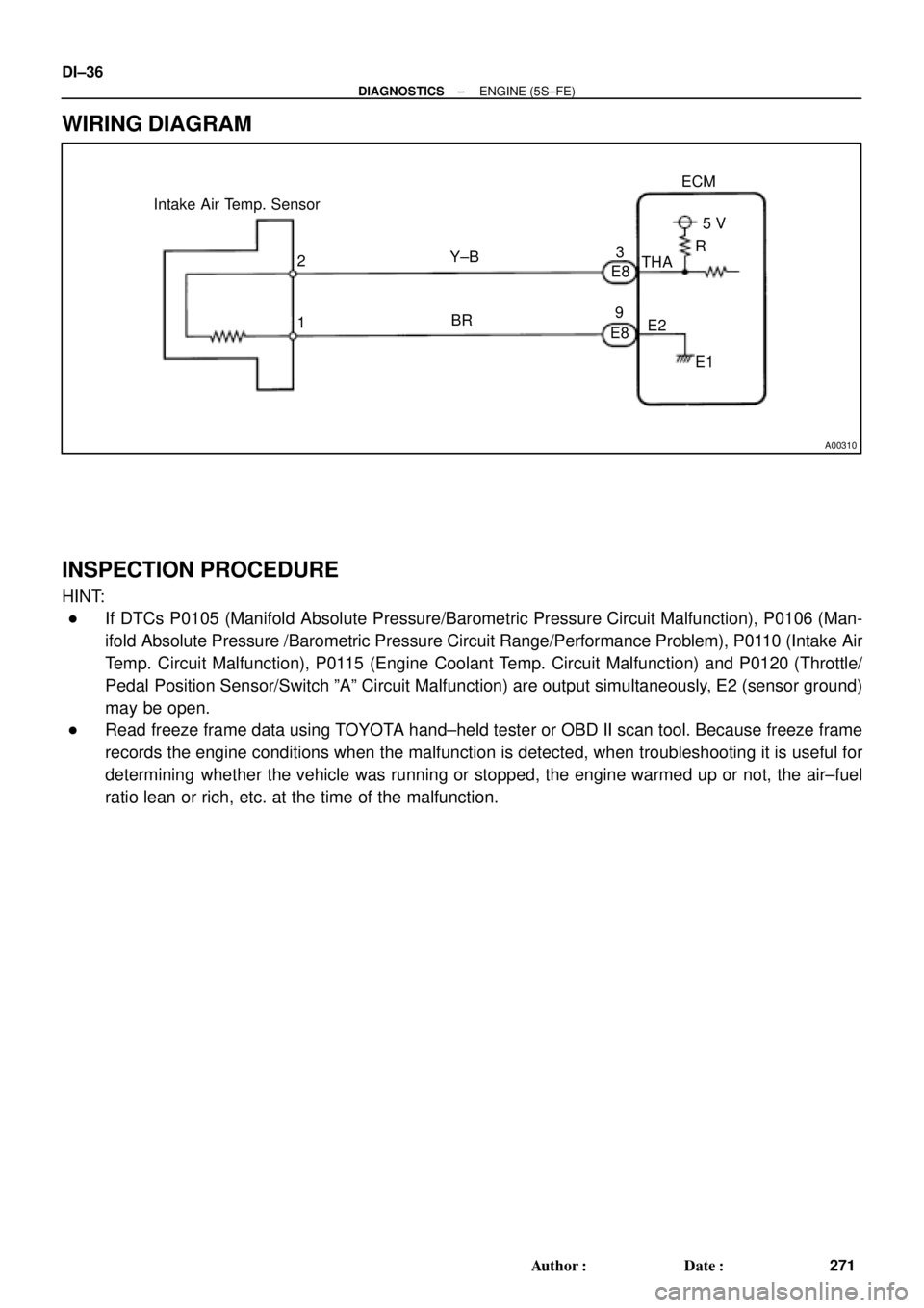
A00310
Intake Air Temp. Sensor
E8
E83
9ECM
5 V
THA
E2
E1 R
Y±B
BR 2
1 DI±36
± DIAGNOSTICSENGINE (5S±FE)
271 Author�: Date�:
WIRING DIAGRAM
INSPECTION PROCEDURE
HINT:
�If DTCs P0105 (Manifold Absolute Pressure/Barometric Pressure Circuit Malfunction), P0106 (Man-
ifold Absolute Pressure /Barometric Pressure Circuit Range/Performance Problem), P0110 (Intake Air
Temp. Circuit Malfunction), P0115 (Engine Coolant Temp. Circuit Malfunction) and P0120 (Throttle/
Pedal Position Sensor/Switch ºAº Circuit Malfunction) are output simultaneously, E2 (sensor ground)
may be open.
�Read freeze frame data using TOYOTA hand±held tester or OBD II scan tool. Because freeze frame
records the engine conditions when the malfunction is detected, when troubleshooting it is useful for
determining whether the vehicle was running or stopped, the engine warmed up or not, the air±fuel
ratio lean or rich, etc. at the time of the malfunction.
Page 2462 of 4770
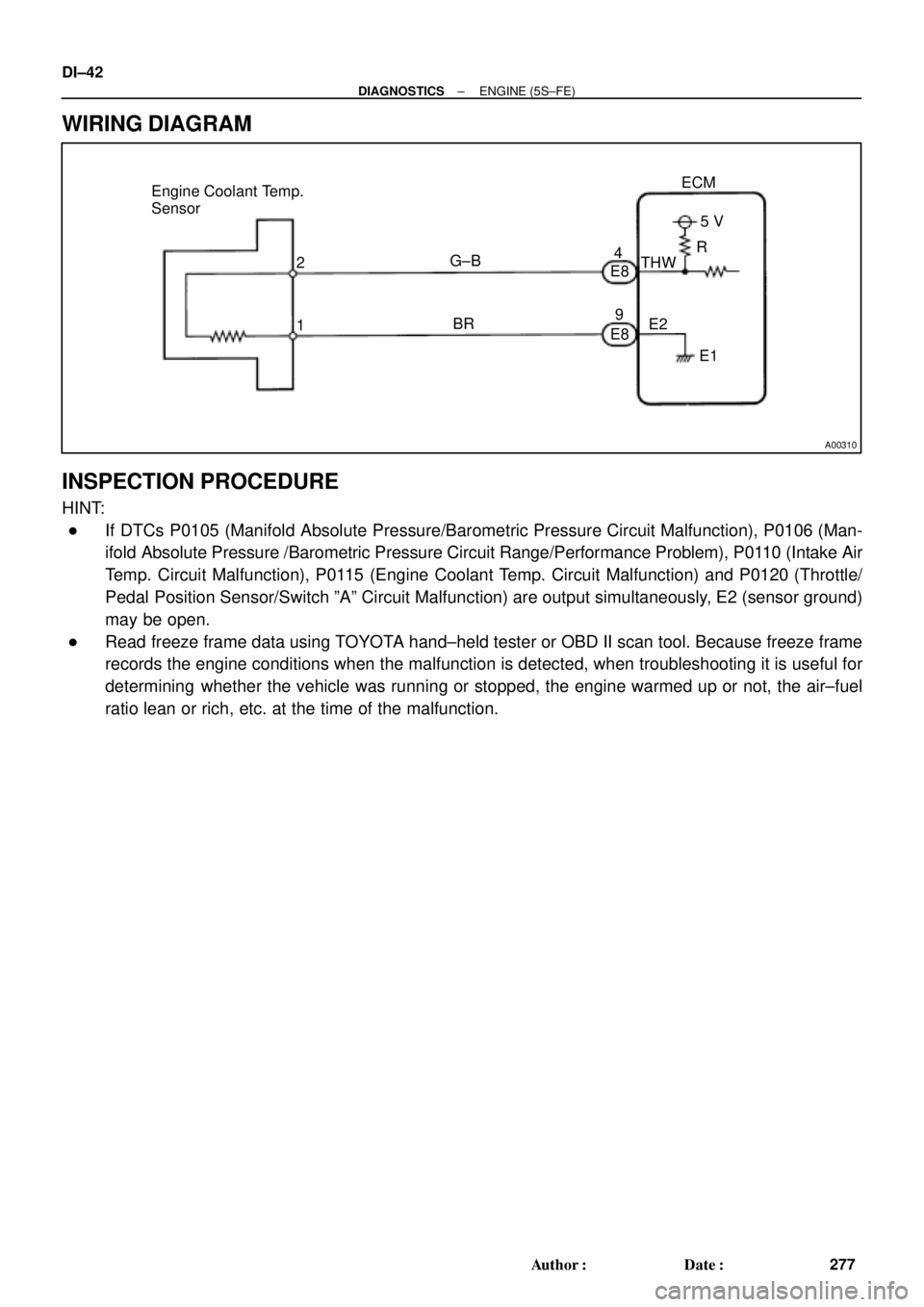
A00310
Engine Coolant Temp.
Sensor
2
1ECM
G±B
BR4
E8
E895 V
THW
E2
E1 R DI±42
± DIAGNOSTICSENGINE (5S±FE)
277 Author�: Date�:
WIRING DIAGRAM
INSPECTION PROCEDURE
HINT:
�If DTCs P0105 (Manifold Absolute Pressure/Barometric Pressure Circuit Malfunction), P0106 (Man-
ifold Absolute Pressure /Barometric Pressure Circuit Range/Performance Problem), P0110 (Intake Air
Temp. Circuit Malfunction), P0115 (Engine Coolant Temp. Circuit Malfunction) and P0120 (Throttle/
Pedal Position Sensor/Switch ºAº Circuit Malfunction) are output simultaneously, E2 (sensor ground)
may be open.
�Read freeze frame data using TOYOTA hand±held tester or OBD II scan tool. Because freeze frame
records the engine conditions when the malfunction is detected, when troubleshooting it is useful for
determining whether the vehicle was running or stopped, the engine warmed up or not, the air±fuel
ratio lean or rich, etc. at the time of the malfunction.
Page 2467 of 4770

DI±47
282 Author�: Date�:
DTC P0116 Engine Coolant Temp. Circuit Range/
Performance Problem
CIRCUIT DESCRIPTION
Refer to DTC P0115 (Engine Coolant Temp. Circuit Malfunc")
± DIAGNOSTICSENGINE (5S±FE)
DI±47
282 Author�: Date�:
DTC P0116 Engine Coolant Temp. Circuit Range/
Performance Problem
CIRCUIT DESCRIPTION
Refer to DTC P0115 (Engine Coolant Temp. Circuit Malfunction) on page DI±41.
DTC No.DTC Detecting ConditionTrouble Area
If THW < ±7°C (19.4°F) or THA < ±7°C (19.4°F) 20 min. or
more after starting engine, engine coolant temp. sensor value
is 30°C (86°F)*1 20°C (48°F)*2 or less
(2 trip detection logic)
If THW ±7°C (19.4°F) and THA � ±7°C (19.4°F) and 10°C
(50°F) at engine start, 5 min. or more after starting engine,
engine coolant temp. sensor value is 30°C (86°F)*1 20°C
(48°F)*2 or less
(2 trip detection logic)
P0116 If THW � 10°C (50°F) and THA � 10°C (50°F) at engine
start, 2 min. or more after starting engine, engine coolant temp.
sensor value is 30°C (86°F)*1 20°C (48°F)*2 or less
(2 trip detection logic)�Engine coolant temp. sensor
�Cooling system
When THW 35°C (95°F) and 60°C (140°F), THA �
±6.7°C (19.9°F) when starting the engine, condition (a) and
(b) continues:
(a) Vehicle speed is changing (Not stable)
(b) Water temperature change is lower than 3°C (37.4°F) from
the water temperature since when sterting the engine
(2 trip detection logic)
*1: Except California Specification vehicles.
*2: Only for California Specification vehicles.
INSPECTION PROCEDURE
HINT:
�If DTCs P0115 (Engine Coolant Temp. Circuit Malfunction) and P0116 (Engine Coolant Temp. Circuit
Range/Performance Problem) are output simultaneously, engine coolant temp. sensor circuit may be
open. Perform troubleshooting of DTC P0115 first.
�Read freeze frame data using TOYOTA hand±held tester or OBD II scan tool. Because freeze frame
records the engine conditions when the malfunction is detected, when troubleshooting it is useful for
determining whether the vehicle was running or stopped, the engine warmed up or not, the air±fuel
ratio lean or rich, etc. at the time of the malfunction.
1 Are there any other codes (besides DTC P0116) being output?
YES Go to relevant DTC chart.
NO
DI00Q±05
Page 2469 of 4770

DI±49
284 Author�: Date�:
DTC P0120 Throttle/Pedal Position Sensor/Switch ºAº
Circuit Malfunction
CIRCUIT DESCRIPTION
The")
P24296
Throttle Position
Sensor
VC
VTA
E2ECM
± DIAGNOSTICSENGINE (5S±FE)
DI±49
284 Author�: Date�:
DTC P0120 Throttle/Pedal Position Sensor/Switch ºAº
Circuit Malfunction
CIRCUIT DESCRIPTION
The throttle position sensor is mounted in the throttle body and
detects the throttle valve opening angle. When the throttle valve
is fully closed, a voltage of approximately 0.3 ~ 0.8 V is applied
to terminal VTA of the ECM. The voltage applied to the termi-
nals VTA of the ECM increases in proportion to the opening
angle of the throttle valve and becomes approximately 3.2 ~ 4.9
V when the throttle valve is fully opened. The ECM judges the
vehicle driving conditions from this signal input from terminal
VTA, and uses it as one of the conditions for deciding the air±
fuel ratio correction, power increase correction and fuel±cut
control etc.
DTC No.DTC Detecting ConditionTrouble Area
P0120
Condition (a) or (b) continues with more than 5 sec.:
(a) VTA < 0.1 V
(b) VTA > 4.9 V�Open or short in throttle position sensor circuit
�Throttle position sensor
�ECM
HINT:
After confirming DTC P0120, use the OBD II scan tool or TOYOTA hand±held tester to confirm the throttle
valve opening percentage.
Throttle valve opening position
expressed as percentage
Trouble Area
Throttle valve fully closedThrottle valve fully open
Trouble Area
0 %0 %VC line open
VTA line open or short
Approx. 100 %Approx. 100 %E2 line open
DI00R±05
Page 2470 of 4770

E8 E810
(*1)
DI±50
± DIAGNOSTICSENGINE (5S±FE)
285 Author�: Date�:
WIRING DIAGRAM")
A03595
Throttle Position Sensor
ECM
E8
E8 1
3
2Y
LG
BR1
11
9VC
VTA
E25 V
*1: w/o Immobiliser
*2: w/ Immobiliser(*2)
E8 E810
(*1)
DI±50
± DIAGNOSTICSENGINE (5S±FE)
285 Author�: Date�:
WIRING DIAGRAM
INSPECTION PROCEDURE
HINT:
�If DTCs P0105 (Manifold Absolute Pressure/Barometric Pressure Circuit Malfunction), P0106 (Man-
ifold Absolute Pressure /Barometric Pressure Circuit Range/Performance Problem), P0110 (Intake Air
Temp. Circuit Malfunction), P0115 (Engine Coolant Temp. Circuit Malfunction) and P0120 (Throttle/
Pedal Position Sensor/Switch ºAº Circuit Malfunction) are output simultaneously, E2 (sensor ground)
may be open.
�Read freeze frame data using TOYOTA hand±held tester or OBD II scan tool. Because freeze frame
records the engine conditions when the malfunction is detected, when troubleshooting it is useful for
determining whether the vehicle was running or stopped, the engine warmed up or not, the air±fuel
ratio lean or rich, etc. at the time of the malfunction.
Page 2474 of 4770

289 Author�: Date�:
DTC P0121 Throttle/Pedal Position Sensor/Switch ºAº
Circuit Range/Performance Problem
CIRCUIT DESCRIPTION
Refer to DTC P0120 (Throttle/Pedal")
DI±54
± DIAGNOSTICSENGINE (5S±FE)
289 Author�: Date�:
DTC P0121 Throttle/Pedal Position Sensor/Switch ºAº
Circuit Range/Performance Problem
CIRCUIT DESCRIPTION
Refer to DTC P0120 (Throttle/Pedal Position Sensor/Switch "A" Circuit Malfunction) on page DI±49.
DTC No.Detection ItemTrouble Area
P0121
After vehicle speed has been exceeded 30 km/h (19 mph)
even once, output value of throttle position sensor is out of
applicable range while vehicle speed between 30 km/h (19
mph) and 0 km/h (0 mph)
(2 trip detection logic)
�Throttle position sensor
INSPECTION PROCEDURE
HINT:
Read freeze frame data using TOYOTA hand±held tester or OBD II scan tool. Because freeze frame records
the engine conditions when the malfunction is detected, when troubleshooting it is useful for determining
whether the vehicle was running or stopped, the engine warmed up or not, the air±fuel ratio lean or rich, etc.
at the time of the malfunction.
1 Are there any other codes (besides DTC P0121) being output?
YES Go to relevant DTC chart.
NO
Replace throttle position sensor.
DI00S±04