Page 206 of 4770
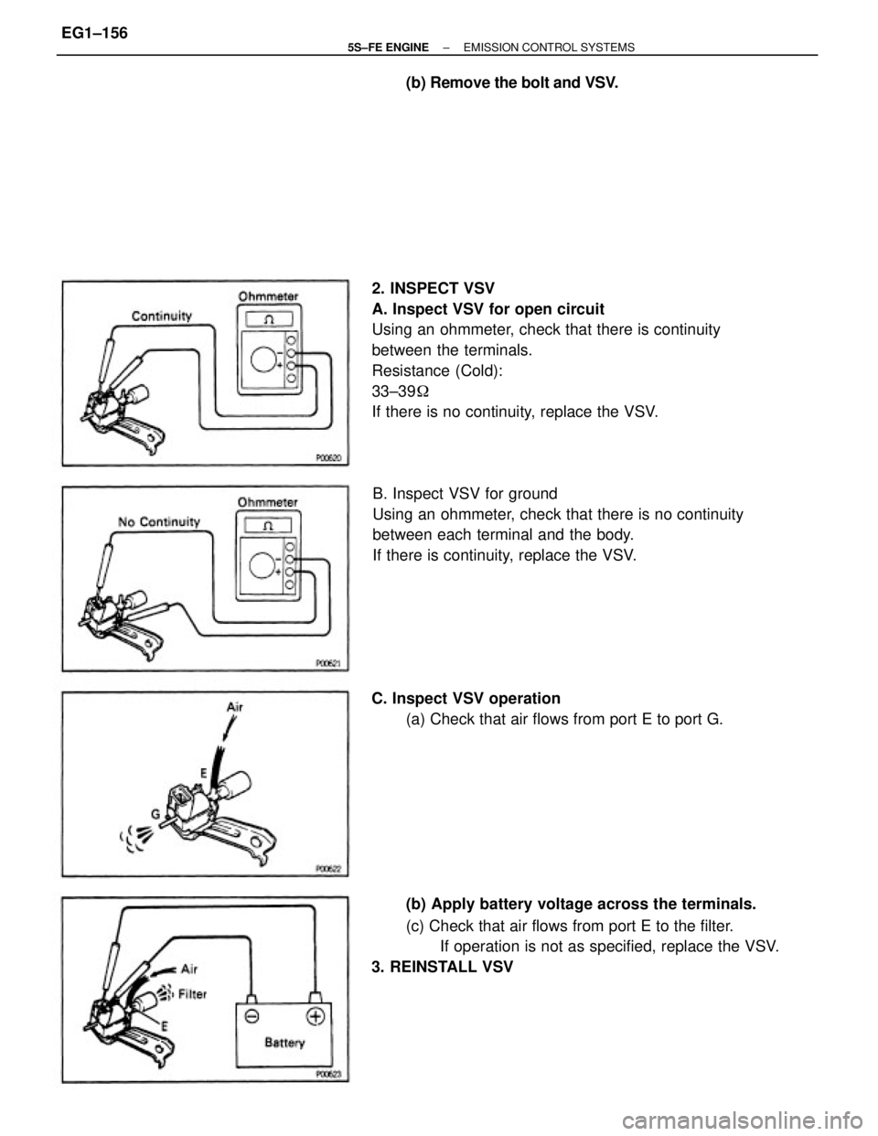
2. INSPECT VSV
A. Inspect VSV for open circuit
Using an ohmmeter, check that there is continuity
between the terminals.
Resistance (Cold):
33±39�
If there is no continuity, replace the VSV.
B. Inspect VSV for ground
Using an ohmmeter, check that there is no continuity
between each terminal and the body.
If there is continuity, replace the VSV.
(b) Apply battery voltage across the terminals.
(c) Check that air flows from port E to the filter.
If operation is not as specified, replace the VSV.
3. REINSTALL VSV C. Inspect VSV operation
(a) Check that air flows from port E to port G. (b) Remove the bolt and VSV.
± 5S±FE ENGINEEMISSION CONTROL SYSTEMSEG1±156
Page 207 of 4770
EGR VALVE INSPECTION
1. REMOVE EGR VALVE
Check for sticking and heavy carbon deposits.
If a problem is found, replace the valve.
2. REINSTALL EGR VALVE WITH NEW GASKET
Nut
Torque: 13 N±m (130 kgf±cm, 9 ft±lbf)
Union nut
Torque: 59 N±m (600 kgf±cm, 43 ft±lbf)
EGR VACUUM MODULATOR INSPECTION
CHECK EGR VACUUM MODULATOR OPERATION
(a) Disconnect the vacuum hoses from ports P, Q and R
of the EGR vacuum modulator.
(b) Block ports P and R with your finger.
(c) Blow air into port Q, and check that the air passes
through to the air filter side freely.
(d) Start the engine, and maintain speed at 2.500 rpm.
(e) Repeat the above test. Check that there is a strong
resistance to air flow.
(f) Reconnect the vacuum hoses to the proper locations.
± 5S±FE ENGINEEMISSION CONTROL SYSTEMSEG1±157
Page 218 of 4770
Air is filtered through the air cleaner and the amount flowing to the air intake chamber is
determined according to the throttle valve opening in the throttle body and the engine speed.
Intake air controlled by the throttle valve opening is distributed from the air intake chamber to the
manifold of each cylinder and is drawn into the combustion chamber.
At low temperatures the IAC valve opens and the air flows through the IAC valve and the throttle
body, into the air intake chamber. During engine warming up, even if the throttle valve is
completely closed, air flows to the air intake chamber, thereby increasing the idle speed (first idle
operation).
The air intake chamber prevents pulsation of the intake air. It also prevents intake air interference
in each cylinder.
AIR INDUCTION SYSTEM
± 5S±FE ENGINEMFI/SFI SYSTEMEG1±168
Page 274 of 4770
VSV INSPECTION (Except California)
1. REMOVE VSV
(a) Disconnect the following connector and hoses:
(1) VSV connector
(2) Vacuum hose (from EGR valve) from port E of
VSV
(3) Vacuum hose (from port ªaº of EGR vacuum
modulator) from port G of VSV
(b) Remove the bolt and VSV.
2. INSPECT VSV
A. Inspect VSV for open circuit
Using an ohmmeter, check that there is continuity
between the terminals.
Resistance (Cold):
33±39�
If there is no continuity, replace the VSV. B. Inspect VSV for ground
Using an ohmmeter, check that there is no continuity
between each terminal and the body.
If there is continuity, replace the VSV.
(b) Apply battery voltage across the terminals.
(c) Check that air flows from port E to the filter.
If operation is not as specified, replace the VSV.
3. REINSTALL VSV C. Inspect VSV operation
(a) Check that air flows from port E to port G.
± 5S±FE ENGINEMFI/SFI SYSTEMEG1±224
Page 275 of 4770
B. Inspect VSV for ground
Using an ohmmeter, check that there is no continuity
between each terminal and the body.
If there is continuity,. replace the VSV.
(b) Apply battery voltage across the terminals.
(c) Check that air flows from port E to the filter.
If operation is not as specified, replace the VSV.
3. REINSTALL VSVC. Inspect VSV operation
(a) Check that air flows from port E to port G.
± 5S±FE ENGINEMFI/SFI SYSTEMEG1±225
Page 277 of 4770
B. Inspect VSV for ground
Using an ohmmeter, check that there is no continuity
between each terminal and the body.
If there is continuity, replace the VSV.
(b) Apply battery voltage across the terminals.
(c) Check that air flows from pipe E to the filter.
If operation is not as specified, replace the VSV. C. Inspect VSV operation
(a) Check that air flows from pipe E to pipe G.
3. REINSTALL VSV
± 5S±FE ENGINEMFI/SFI SYSTEMEG1±227
Page 319 of 4770

A pressure feeding lubrication system has been adopted to supply oil to the moving parts of this
engine. The lubrication system consists of an oil pan, oil pump, oil filter and other external parts
which supply oil to the moving parts in the engine block. The oil circuit is shown in the illustration
at the top of the previous page. Oil from the oil pan is pumped up by the oil pump. After it passes
through the oil filter, it is through the various oil holes in the crankshaft and cylinder block. After
passing through the cylinder block and performing its lubricating function, the oil is returned by
gravity to the oil pan. A dipstick on the center left side of the cylinder block is provided to check
the oil level.
OIL PUMP
The oil pump pumps up oil from the oil pan and feeds it under pressure to the various parts of the
engine. An oil strainer is mounted in front of the inlet to the oil pump to remove impurities. The
oil pump itself is a trochoid type pump, inside of which is a drive rotor and a driven rotor. When
the drive rotor rotates, the driven rotor rotates in the same direction, and since the axis of the
drive rotor shaft is different from the center of the driven rotor, the space between the two rotors
changes as they rotate. Oil is drawn in when the space widens and is discharged when the space
becomes narrow.
OIL PRESSURE REGULATOR (RELIEF VALVE)
At high engine speeds, the engine oil supplied by the oil pump exceeds the capacity of the engine
to utilize it. For that reason, the oil pressure regulator works to prevent an oversupply of oil.
During normal oil supply, a coil spring and valve keep the bypass closed, but when too much oil
is being fed, the pressure becomes extremely high, overpowering the force of the spring and
opening the valves. This allows the excess oil to flow through the valve and return to the oil pan.
OIL FILTER
The oil filter is a full flow type filter with a relief valve built into the paper filter element. Particles
of metal from wear, airborne dirt, carbon and other impurities can get into the oil during use and
could cause accelerated wear or seizing if allowed to circulate through the engine. The oil filter,
integrated into the oil line, removes these impurities as the oil passes through it. The filter is
mounted outside the engine to simplify replacement of the filter element. A relief valve is also
included ahead of the filter element to relieve the high oil pressure in case the filter element
becomes clogged with impurities. The relief valve opens when the oil pressure overpowers the
force of the spring. Oil passing through the relief valve bypasses the oil filter and flows directly
into the main oil hole in the engine.
± 5S±FE ENGINELUBRICATION SYSTEMEG1±269
Page 360 of 4770
BASIC INSPECTION
When the normal code is displayed in the diagnostic trouble code check, troubleshooting should be
performed in the order for all possible circuits to be considered as the causes of the problems.
In many cases, by carrying out the basic engine check shown in the following flow chart, the location
causing the problem can be found quickly and efficiently. Therefore, use of this check is essential in en-
gine troubleshooting.
Remove air filter.
Visually check that the air filter is not excessively
damaged or oily.
If necessary, clean the air filter with compressed
air. First blow from inside thoroughly, then blow
off outside of the air filter.
Is battery positive voltage 11 V or more when engine is stopped?
Proceed to matrix chart of problem
symptoms on page EG1±327.
Is engine cranked ?
Does engine start
Charge or replace battery.
Check air filter.
Repair or replace. Go to step
Go to step
YESYES
YES
± 5S±FE ENGINEBASIC INSPECTIONEG1±310


1. REMOVE VSV
(a) Disconnect the following connector and hoses:
(1) VSV connector
(2) Vacuum hose (from EGR valve) from port E of
VSV
(3) Vacuum hose (fr")
 Apply battery voltage across the termin")
 Apply battery voltage across the termina")
