Page 3424 of 4770

A07368
Spark Plug
Grommet
Cylinder Head Cover
Gasket
Camshaft Bearing Cap
� Camshaft Oil Seal
Camshaft Timing Pulley
Snap Ring
Wave Washer
Camshaft Position Sensor Connector
Camshaft Position Sensor Assembly
Wire Clamp
No. 3 Timing Belt Cover
No.2 Timing Belt Cover� Oil Seal
Valve Guide
Bushing
Cylinder
Head
Gasket Adjusting Shim
Valve Lifter
Keeper
Spring Retainer
Valve Spring
Spring Seat
Valve
LH Engine
Hanger
Semi±Circular
Plug
Oil Pressure
Switch
Camshaft Gear Spring
Camshaft Sub±Gear
Semi±Circular
Plug
Tension Spring
No.1 Idler Pulley
*
1
GasketTiming Belt
Cylinder Head Intake
CamshaftExhaust
Camshaft
Wire
Clamp
Wire
Clamp
Generator Bracket and
RH Engine Hanger
Assembly
N´m (kgf´cm, ft´lbf)
*
2 For use with SST
� Non±reusable part
18 (180, 13)
44 (450, 33)
19 (190, 14)
*
237 (380, 27)1st 49 (500, 36)
2nd Turn 90°
42 (425, 31)
x 10�
�
: Specified torque
See page EM±53
*1
Replace only if damaged
54 (550, 40)
EM±32
± ENGINE MECHANICAL (5S±FE)CYLINDER HEAD
1204 Author�: Date�:
Page 3430 of 4770
CYLINDER HEAD
1210 Author�: Date�:
(2) Secure the exhaust camshaft sub±gear to drive
gear w")
P03445
Drive Gear
Service
Bolt
Sub±Gear
P03356
P03241
3
26 54
1
P03357
EM±38
± ENGINE MECHANICAL (5S±FE)CYLINDER HEAD
1210 Author�: Date�:
(2) Secure the exhaust camshaft sub±gear to drive
gear with a service bolt.
Recommended service bolt:
Thread diameter6 mm
Thread pitch1.0 mm
Bolt length16 ± 20 mm (0.63 ± 0.79 in.)
HINT:
When removing the camshaft, make sure that the torsional
spring force of the sub±gear has been eliminated by the above
operation.
(3) Remove the 2 bolts and rear bearing cap.
(4) Uniformly loosen and remove the 6 bolts on the
No.1, No.2 and No.4 bearing caps in several
passes, in the sequence shown.
NOTICE:
Do not remove the No.3 bearing cap bolts at this stage.
(5) Remove the No.1, No.2 and No.4 bearing caps.
(6) Alternately loosen and remove the 2 bolts on the
No.3 bearing cap.
HINT:
�As the 2 No.3 bearing cap bolts are loosened, make sure
that the camshaft is lifted out straight and level.
�If the camshaft is not being lifted out straight and level, re-
tighten the 2 No.3 bearing cap bolts. Then reverse the or-
der of above steps from (6) to (1) and reset the knock pin
of the intake camshaft at 10 ± 45° BTDC, and repeat
steps from (2) to (6) once again.
NOTICE:
Do not pry on or attempt to force the camshaft with a tool
or other object.
(7) Remove the No.3 bearing cap and exhaust cam-
shaft.
Page 3431 of 4770
CYLINDER HEAD
EM±39
1211 Author�: Date�:
(b) Remove the intake camshaft.
(1) Set the knock pin of the intak")
P03358
8 0 ± 11 5°
Knock
Pin
P03359
P03360
1 2
3 45 6
P03361
± ENGINE MECHANICAL (5S±FE)CYLINDER HEAD
EM±39
1211 Author�: Date�:
(b) Remove the intake camshaft.
(1) Set the knock pin of the intake camshaft at 80 ±
11 5° BTDC of camshaft angle.
HINT:
The above angle allows the No.1 and No.3 cylinder cam lobes
of intake camshaft to push their valve lifters evenly.
(2) Remove the 2 bolts, front bearing cap and oil seal.
(3) Uniformly loosen and remove the 6 bolts on the
No.1, No.3 and No.4 bearing caps in several
passes, in the sequence shown.
NOTICE:
Do not remove the No.2 bearing cap bolts at this stage.
(4) Remove the No.1, No.3 and No.4 bearing caps.
(5) Alternately loosen and remove the 2 bolts on the
No.2 bearing cap.
HINT:
�As the 2 No.2 bearing cap bolts are loosened, make sure
that the camshaft is lifted out straight and level, after
breaking adhesion on the front bearing cap.
�If the camshaft is not being lifted out straight and level, re-
tighten the 2 No.2 bearing cap bolts. Reverse the order
of above steps from (5) to (1) and reset the knock pin of
the intake camshaft at 80 ± 115° BTDC, and repeat steps
from (2) to (5) once again.
NOTICE:
Do not pry on or attempt to force the camshaft with a tool
or other object.
(6) Remove the No.2 bearing cap and camshaft.
Page 3440 of 4770
CYLINDER HEAD
1220 Author�: Date�:
(e) Inspect the journal oil clearance.
(1) Clean the bearing caps and camshaft journals.
(")
EM3371
Plastigage
P00259
EM3310
P00263
EM±48
± ENGINE MECHANICAL (5S±FE)CYLINDER HEAD
1220 Author�: Date�:
(e) Inspect the journal oil clearance.
(1) Clean the bearing caps and camshaft journals.
(2) Check that bearings for flaking and scoring.
If the bearings are damaged, replace the bearing caps and cyl-
inder head as a set.
(3) Place the camshafts on the cylinder head.
(4) Lay a strip of Plastigage across each of the cam-
shaft journals.
(5) Install the bearing caps. (See page EM±53)
NOTICE:
Do not turn the camshaft.
(6) Remove the bearing caps.
(7) Measure the Plastigage at its widest point.
Standard oil clearance:
0.025 ± 0.062 mm (0.0010 ± 0.0024 in.)
Maximum oil clearance: 0.10 mm (0.0039 in.)
If the oil clearance is greater than maximum, replace the cam-
shaft. If necessary, replace the bearing caps and cylinder head
as a set.
(8) Completely remove the Plastigage.
(f) Inspect the camshaft thrust clearance.
(1) Install the camshaft. (See page EM±53)
(2) Using a dial indicator, measure the thrust clearance
while moving the camshaft back and forth.
Standard thrust clearance:
Intake0.045 ± 0.100 mm (0.0018 ± 0.0039 in.)
Exhaust0.030 ± 0.085 mm (0.0012 ± 0.0033 in.)
Maximum thrust clearance:
Intake0.12 mm (0.0047 in.)
Exhaust0.10 mm (0.0039 in.)
If the thrust clearance is greater than maximum, replace the
camshaft. If necessary, replace the bearing caps and cylinder
head as a set.
Page 3447 of 4770

Seal
Packing
P03370
P03371
17
5
3
98
2
6
4
10
P03372
SST
± ENGINE MECHANICAL (5S±FE)CYLINDER HEAD
EM±55
1227 Author�: Date�:
(a) Inst")
P03369
80 ±115°
Knock
Pin
EM3373
2 ± 3 mm
(0.08 ± 0.12 in.)
Seal
Packing
P03370
P03371
17
5
3
98
2
6
4
10
P03372
SST
± ENGINE MECHANICAL (5S±FE)CYLINDER HEAD
EM±55
1227 Author�: Date�:
(a) Install the intake camshaft.
(1) Apply MP grease to the thrust portion of the cam-
shaft.
(2) Place the intake camshaft at 80 ± 115° BTDC of
camshaft angle on the cylinder head.
HINT:
The above angle arrows the No.1 and No.3 cylinder cam lobes
of the intake camshaft to push their valve lifters evenly.
(3) Apply seal packing to the No.1 bearing cap as
shown.
Seal packing: Part No. 08826±00080 or equivalent
(4) Install the bearing caps in their proper locations.
(5) Apply a light coat of engine oil on the threads and
under the heads of the bearing cap bolts.
(6) Install and uniformly tighten the 10 bearing cap
bolts in several passes, in the sequence shown.
Torque: 19 N´m (190 kgf´cm, 14 ft´lbf)
(7) Apply MP grease to a new oil seal lip.
(8) Using SST and a hammer, tap in the oil seal.
SST 09223±46011
Page 3448 of 4770
CYLINDER HEAD
1228 Author�: Date�:
(b) Install the exhaust c")
P03281
10 ± 45°
Knock
Pin
P03373
Assembly
Reference Mark
Timing
Mark
P03374
P03375
1 2
3 410
5 6
8
79 EM±56
± ENGINE MECHANICAL (5S±FE)CYLINDER HEAD
1228 Author�: Date�:
(b) Install the exhaust camshaft.
(1) Set the knock pin of the intake camshaft at 10 ± 45°
BTDC of camshaft angle.
HINT:
The above angle allows the No.2 and No.4 cylinder cam lobes
of the exhaust camshaft to push their valve lifters evenly.
(2) Apply MP grease to the thrust portion of the cam-
shaft.
(3) Engage the exhaust camshaft gear to the intake
camshaft gear by matching the timing marks on
each gear.
(4) Roll down the exhaust camshaft onto the bearing
journals while engaging gears with each other.
NOTICE:
There are also assembly reference marks on each gear as
shown in the illustration. Do not use these marks.
(5) Turn the intake camshaft clockwise or counterclock-
wise a little until the exhaust camshaft sits in the
bearing journals evenly without rocking the cam-
shaft on the bearing journals.
NOTICE:
It is very important to replace the camshaft in the bearing
journals evenly while tightening bearing caps in the subse-
quent steps.
(6) Install the bearing caps in their proper locations.
(7) Apply a light coat of engine oil on the threads and
under the heads of the bearing cap bolts.
(8) Install and uniformly tighten the 10 bearing cap
bolts in several passes, in the sequence shown.
Torque: 19 N´m (190 kgf´cm, 14 ft´lbf)
Page 3475 of 4770
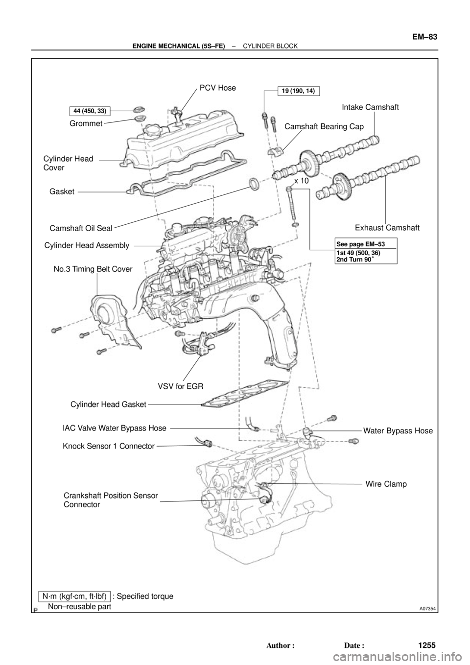
A07354
Grommet
Cylinder Head
Cover
Gasket
� Camshaft Oil Seal
Cylinder Head Assembly
No.3 Timing Belt Cover
Crankshaft Position Sensor
ConnectorWire Clamp Water Bypass Hose Exhaust Camshaft Intake Camshaft
Camshaft Bearing Cap PCV Hose
� Cylinder Head Gasket
IAC Valve Water Bypass Hose
Knock Sensor 1 Connector
N´m (kgf´cm, ft´lbf)
� Non±reusable part
44 (450, 33)
19 (190, 14)
VSV for EGR
: Specified torquex 10
1st 49 (500, 36)
2nd Turn 90° See page EM±53
± ENGINE MECHANICAL (5S±FE)CYLINDER BLOCK
EM±83
1255 Author�: Date�:
Page 3537 of 4770
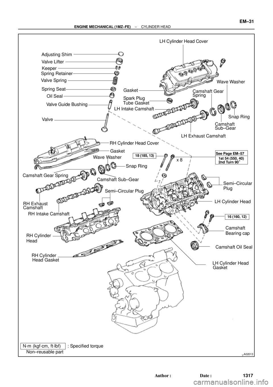
A02013
Adjusting Shim
Valve Lifter
Keeper
Spring Retainer
Valve Spring
Spring Seat
� Oil Seal
Valve � Valve Guide BushingLH Cylinder Head Cover
GasketWave Washer
Camshaft Gear
Spring
� Spark Plug
Tube Gasket
LH Intake Camshaft
Snap Ring
Camshaft
Sub±Gear
LH Exhaust Camshaft
RH Cylinder Head Cover
Gasket
RH Intake CamshaftCamshaft Sub±GearSnap Ring
Camshaft Gear Spring
RH Exhaust
CamshaftWave Washer
Semi±Circular PlugSemi±Circular
Plug
LH Cylinder Head
Camshaft
Bearing cap
� Camshaft Oil Seal RH Cylinder
Head
� RH Cylinder
Head Gasket
� LH Cylinder Head
Gasket x 8
N´m (kgf´cm, ft´lbf) : Specified torque
� Non±reusable part
18 (185, 13)
16 (160, 12) See Page EM±57
1st 54 (550, 40)
2nd Turn 90°
± ENGINE MECHANICAL (1MZ±FE)CYLINDER HEAD
EM±31
1317 Author�: Date�: