Page 119 of 4770
 Apply MP grease to the thrust portion of the cam±
shaft.
(b) Place the intake camshaft at 80±1155 BTDC of cam±
shaft angle, on the cylinder head.
HINT: The above angl")
A. Install intake camshaft
(a) Apply MP grease to the thrust portion of the cam±
shaft.
(b) Place the intake camshaft at 80±1155 BTDC of cam±
shaft angle, on the cylinder head.
HINT: The above angle arrows the No.1 and No.3
cylinder cam lobes of the intake camshaft to push
their valve lifters evenly. 4. INSTALL CAMSHAFTS
NOTICE: Since the thrust clearance of the camshaft is
small, the camshaft must be kept level while it is being
installed. If the camshaft is not kept level, the portion of
the cylinder head receiving the shaft thrust may crack or
be damaged, causing the camshaft to seize or break. To
avoid this, the following steps should be carried out.
(d) Insert a service bolt (A) into the service hole of the
camshaft sub gear.
(e) Using a screwdriver, align the holes of the camshaft
main gear and sub gear by turning camshaft sub gear
clockwise, and install a service bolt (13).
NOTICE: Be careful not to damage the camshaft.
(c) Apply seal packing to the No. 1 bearing cap as shown.
Seal packing:
Part No.08826 ±00080 or equivalent (c) Using snap ring pliers, install the snap ring.
± 5S±FE ENGINEENGINE MECHANICALEG1±69
Page 120 of 4770
B. Install exhaust camshaft
(a) Set the knock pin of the intake camshaft at 10±455
BTDC of camshaft angle.
HINT: The above angle allows the No.2 and No.4
cylinder cam lobes of the exhaust camshaft to push
their valve lifters evenly.(e) Apply a light coat of engine oil on the threads and
under the heads of the bearing cap bolts.
(f) Install and uniformly tighten the 10 bearing cap bolts
in several passes, in the sequence shown.
Torque: 19 N±m (190 kgf±cm, 14 ft±lbf)
(h) Using SST, tap in the oil seal.
SST 09223±4601 1 (d) Install the bearing caps in their proper locations.
(g) Apply MP grease to a new oil seal lip.
± 5S±FE ENGINEENGINE MECHANICALEG1±70
Page 121 of 4770
 Apply MP grease to the thrust portion of the cam±
shaft.
(c) Engage the exhaust camshaft gear to the intake cam±
shaft gear by matching the timing marks on each gear.
(d) Roll down the exhaust c")
(b) Apply MP grease to the thrust portion of the cam±
shaft.
(c) Engage the exhaust camshaft gear to the intake cam±
shaft gear by matching the timing marks on each gear.
(d) Roll down the exhaust camshaft onto the bearing
journals while engaging gears with each other.
NOTICE: There are also assembly reference marks on
each gear as shown in the Illustration. Do not use these
marks.
5. CHECK AND ADJUST VALVE CLEARANCE
(See page EG1±12)
Turn the camshaft and position the cam lobe upward,
and check and adjust the valve clearance.
Valve clearance (Cold):
Intake
0.19 ± 0.29 mm (0.007 ± 0.011 In.)
Exhaust
0.28 ± 0.38 mm (0.011 ± 0.015 In.)(e) Turn the intake camshaft clockwise or counterclockwise little
by little until the exhaust camshaft sits in
the bearing journals evenly without rocking the cam±
shaft on the bearing journals.
NOTICE: It is very important to replace the camshaft in
the bearing journals evenly while tightening bearing caps
in the subsequent steps.
(f) Install the bearing caps in their proper locations.
(g) Apply a light coat of engine oil on the threads and
under the heads of the bearing cap bolts.
(h) Install and uniformly tighten the 10 bearing cap bolts
in several passes, in the sequence shown.
Torque: 19 N±m (190 kgf±cm, 14 ft±lbf)
(i) Remove the service bolt (B).
± 5S±FE ENGINEENGINE MECHANICALEG1±71
Page 194 of 4770

No. 1 balance shaft housing x No. 2 balance shaft housing (2nd)
FR engine mounting insulator x Front suspension member
RR engine mountin")
No. 1 balance shaft housing x No. 2 balance shaft housing (1st)
No. 1 balance shaft housing x No. 2 balance shaft housing (2nd)
FR engine mounting insulator x Front suspension member
RR engine mounting insulator x Front suspension member Exhaust manifold stay x FR engine mounting insulator No. 1 air intake chamber stay x Intake manifold
RR engine mounting insulator x Cylinder block
FR engine mounting insulator x Cylinder block No. 1 air intake chamber stay x Cylinder head
No. 1 exhaust manifold stay x Cylinder block
Connecting rod cap x Connecting rod (2nd) Connecting rod cap x Connecting rod (1 st)
LH engine mounting insulator x Transaxle No. 1 exhaust manifold stay x WU ±TWC Water bypass pipe x Water pump cover
Fuel inlet hose x Fuel filter (Union bolt) No. 3 timing belt cover x Cylinder head
Intake manifold stay x Intake manifoldCamshaft bearing cap x Cylinder head
Intake manifold stay x Cylinder blockCylinder head x Cylinder block (2nd)
Rear oil seal retainer x Cylinder block Exhaust manifold stay x WU ±TWC
PS pump bracket x Cylinder block Main bearing cap x Cylinder block Generator bracket x Cylinder head
A/C compressor x Cylinder block Pulsation damper x Delivery pipe
Exhaust manifold x Cylinder head
Engine balancer x Cylinder block
Front exhaust pipe x WU ±TWC Spark plug tube x Cylinder head
Rear end plate x Cylinder block Throttle body x Intake manifold Intake manifold x Cylinder heedEngine hanger x Cylinder head
Drive plate x Crankshaft (A/T)Knock sensor x Cylinder block Delivery pipe x Cylinder head
PS pump x PS pump bracketWU±TWC x Exhaust manifold
Flywheel x Crankshaft (M/T) Water outlet x Cylinder headEGR valve x intake manifold
EGR pipe x Cylinder head
± 5S±FE ENGINEENGINE MECHANICALEG1±144
Page 1123 of 4770

Maintenance Log.
. Cars & Sienna
SCHEDULED MAINTENANCE LOGS31
60,000 Miles or 48 Months
❑Replace engine air filter❑Replace engine coolant
❑Replace engine oil and oil filter❑Rotate tires
❑Replace platinum spark plugs1
❑Replace non-platinum spark plugs (Corolla, Paseo, Tercel)1
❑Repack front wheel bearings (Paseo, Tercel)
❑Re-torque drive shaft flange bolts (Sienna)
❑Inspect the following:__
Ball joints and dust covers__
Drive shaft boots
__
Brake lines and hoses__
Engine valves
__
Brake linings/drums and brake pads/discs__
Exhaust pipes and mountings
__
Charcoal canister
2__
Fuel tank cap gasket
__
Differential oil__
Steering gear box
__
Drive belts__
Steering linkage
__
Fuel lines and connections, fuel tank band__
Transmission fluid or oil
and fuel tank vapor vent system hoses
Additional Maintenance Items for Special Operating Conditions:*❑Inspect nuts and bolts on body and chassis❑Replace differential oil❑Replace transmission fluid or oil
Date: __________________
Mileage: _______________
60,000 Miles or 48 Months
60,000 Miles or 48 Months
DEALER SERVICE VERIFICATION
1Required under the terms of the Emission Control Warranty.2Inspect at 60,000 miles or 72 months, whichever comes first, for Avalon, 6-cyl. Camry,
6-cyl. Camry Solara, Paseo, Sienna and Tercel. Required only for vehicles in California,
Massachusetts and New York.
Page 1131 of 4770

Maintenance Log.
. Cars & Sienna
SCHEDULED MAINTENANCE LOGS39
120,000 Miles or 96 Months
❑Replace engine air filter❑Replace engine coolant
❑Replace engine oil and oil filter❑Rotate tires
❑Replace platinum spark plugs1
❑Replace non-platinum spark plugs (Corolla, Paseo, Tercel)1
❑Repack front wheel bearings (Paseo, Tercel)
❑Re-torque drive shaft flange bolts (Sienna)
❑Inspect the following:__
Ball joints and dust covers__
Drive shaft boots
__
Brake lines and hoses__
Engine valves
__
Brake linings/drums and brake pads/discs__
Exhaust pipes and mountings
__
Charcoal canister
2__
Fuel tank cap gasket
__
Differential oil__
Steering gear box
__
Drive belts__
Steering linkage
__
Fuel lines and connections, fuel tank band__
Transmission fluid or oil
and fuel tank vapor vent system hoses
Additional Maintenance Items for Special Operating Conditions:*❑Inspect nuts and bolts on body and chassis❑Replace differential oil❑Replace transmission fluid or oil
Date: __________________
Mileage: _______________
120 Months
❑Inspect SRS Air Bag
Date: __________________
Mileage: _______________
120,000 Miles or 96 Months
120,000 Miles or 96 Months
120 Months
120 Months
DEALER SERVICE VERIFICATION
1Required under the terms of the Emission Control Warranty.2Inspect at 120,000 miles or 144 months, whichever comes first, for Avalon, 6-cyl. Camry,
6-cyl. Camry Solara, Paseo, Sienna and Tercel. Required only for vehicles in California,
Massachusetts and New York.DEALER SERVICE VERIFICATION
Page 3410 of 4770
TIMING BELT
1190 Author�: Date�:
10. SET NO.1 CYLINDER TO TDC/COMPRESSION
(a) Turn the crankshaft pulley, an")
S05587
Turn
S05580
A02585
S05583
Pry
Move
S05593
SSTSST EM±18
± ENGINE MECHANICAL (5S±FE)TIMING BELT
1190 Author�: Date�:
10. SET NO.1 CYLINDER TO TDC/COMPRESSION
(a) Turn the crankshaft pulley, and align its groove with timing
mark º0º of the No.1 timing belt cover.
(b) Check that the hole of the camshaft timing pulley is
aligned with the timing mark of the bearing cap.
If not, turn the crankshaft 1 revolution (360°).
11. REMOVE TIMING BELT FROM CAMSHAFT TIMING
PULLEY
HINT:
When re±using timing belt:
Affix the matching marks on the timing belt and the camshaft
timing pulley, and the timing belt and the No. 1 timing belt cover.
(a) Loosen the mounting bolt of the No.1 idler pulley, and shift
the pulley toward the left as far as it will go, and temporari-
ly tighten it.
(b) Remove the timing belt from the camshaft timing pulley.
12. REMOVE CAMSHAFT TIMING PULLEY
(a) Using SST, loosen the pulley bolt.
SST 09249±63010, 09960±10010 (09962±01000,
09963±01000)
(b) Remove the bolt and timing pulley.
Page 3418 of 4770
S05594
SST
A02592
S05582
S05931
S05581
Loosen EM±26
± ENGINE MECHANICAL (5S±FE)TIMING BELT
1198 Author�: Date�:
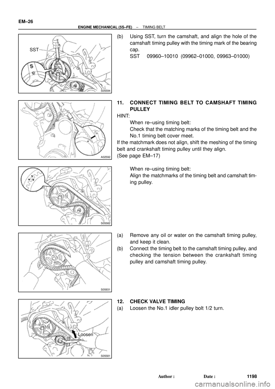
(b) Using SST, turn the camshaft, and align the hole of the
camshaft timing pulley with the timing mark of the bearing
cap.
SST 09960±10010 (09962±01000, 09963±01000)
11. CONNECT TIMING BELT TO CAMSHAFT TIMING
PULLEY
HINT:
�When re±using timing belt:
Check that the matching marks of the timing belt and the
No.1 timing belt cover meet.
If the matchmark does not align, shift the meshing of the timing
belt and crankshaft timing pulley until they align.
(See page EM±17)
�When re±using timing belt:
Align the matchmarks of the timing belt and camshaft tim-
ing pulley.
(a) Remove any oil or water on the camshaft timing pulley,
and keep it clean.
(b) Connect the timing belt to the camshaft timing pulley, and
checking the tension between the crankshaft timing
pulley and camshaft timing pulley.
12. CHECK VALVE TIMING
(a) Loosen the No.1 idler pulley bolt 1/2 turn.
 Set the knock pin of the intake camshaft at 10±455
BTDC of camshaft angle.
HINT: The above angle allows the No.2 and No.4
cylinder cam lobes of the exhaust camshaft to")