Page 5 of 4770

1
GENERAL 2000 FEATURES
170EG08
VSV
(for Canister
Closed Valve)VSV
(for
EVAP)
Fuel Tank
Purge Line
Fresh Air LineVapor Pressure
SensorVSV
(for Pressure Switching Valve)
Chacoal Canister
Fresh Air Valve
Drain 2
ENGINE
�EVAPORATIVE EMISSION CONTROL SYSTEM
The method for detecting evaporative emission leaks has been changed from the previous internal pressure
monitor type to the vacuum type. The vacuum type forcefully introduces the purge vacuum into the entire
system and a leak is detected by monitoring the transitions in pressure. The changes associated with this sys-
tem are as follows:
�A VSV for canister closed valve has been added to the fresh air introduction line.
�The 3-way VSV for vapor pressure sensor has been discontinued, and a VSV for pressure switching valve
has been added.
�The sensing position of the vapor pressure sensor has been changed from the charcoal canister to the fuel
tank in order to enhance the precision of the vapor pressure sensor.
�The fresh air valve characteristics of the charcoal canister have been changed.
�Diagnostic trouble codes (DTCs) have been added. For details on the DTCs, refer to the each Repair Manu-
al.
Page 372 of 4770
IG switch ON and apply vacuum to the
throttle opener. Throttle valve fully closed. ECM (Except California specification vehicles with M/T)
STANDARD VALUE OF EC
Idling, Engine coolant temp, 80�C (176�F) IG switch 0 N
Throttle valve fully closed
IG switch ON
Throttle valve fully openIG switch ON
Throttle valve fully open
Idling, Intake air temp. 20�C (68�F)
Pulse generation
(See page EG1±347)
Pulse generation
(See page EG1±336)
Pulse generation
(See page EG1±336) Pulse generation
(See page EG1±347)
TERMINALS
Symbols (Terminals No.)
STD Voltage (V)
Pulse generation Wiring Color
IG switch ON IG switch ON
IG switch ONIG switch ON
IG switch ONCondition
Below 2.0Always
Idling IdlingIdling
IdlingIdlingIdling
± 5S±FE ENGINESTANDARD VALUE OF ECM TERMINALSEG1±322
Page 374 of 4770

ECM (California specification vehicles and except California specification vehicles with A/T)
STANDARD VALUE OF ECM TERMINALS (Cont'd)
*�: Only for California specification vehicles.
*�: Except California specification vehicles with A/T.IG switch ON and apply vacuum to the
throttle opener. Throttle valve fully closed.
Idling, Engine coolant temp. 80�C (176�F) IG switch ON
Throttle valve fully closedIG switch ON
Throttle valve fully open
IG switch ON
Throttle valve fully open
Idling, Intake air temp. 20�C (68�F)
Pulse generation
(See page EG1±410)
Pulse generation
(See page EG1±341)
Pulse generation
(See page EG1±336) Pulse generation
(See page EG1±341) Pulse generation
(See page EG1±347) Pulse generation
(See page EG1±347)
Pulse generation
(See page EG1±336) Symbols (Terminals No.)*3
STD Voltage (V) Wiring Color
IG switch ON IG switch ONIG switch ON
IG switch ONlG switch ONCondition
Below 2.0Always
Idling Idling
Idling Idling
Idling Idling
Idling
Idling
± 5S±FE ENGINESTANDARD VALUE OF ECM TERMINALSEG1±324
Page 428 of 4770

INSPECTION PROCEDURE
HINT: If diagnostic trouble code ª22º (engine coolant temperature sensor circuit), ª24º (intake air
temperature sensor circuit), ª31º (manifold absolute pressure sensor circuit) and ª41 ª (throttle
position sensor circuit) are output simultaneously, E2 (sensor ground) may be open.
(1) Remove glove compartment.
(See page EG1±234).
(2) Disconnect the vacuum hose from the throt±
tle body, then apply vacuum to the throttle
opener (See page EG1±204).
(3) Turn ignition switch ON.
Measure voltage between terminals VTA, IDL and
E2 of engine control module connector when the
throttle valve is opened gradually from the closed
condition.
Check voltage between terminals VTA, IDL and E2 of engine
control module connector.
The voltage should increase steadily in propor±
tion to the throttle valve opening angle.
Check for momentary interruption
(See page EG1±309).
Throttle Valve
Fully Closed
Fully OpenVTA ± E2 Terminal
IDL ± E2
± 5S±FE ENGINECIRCUIT INSPECTIONEG1±378
Page 449 of 4770

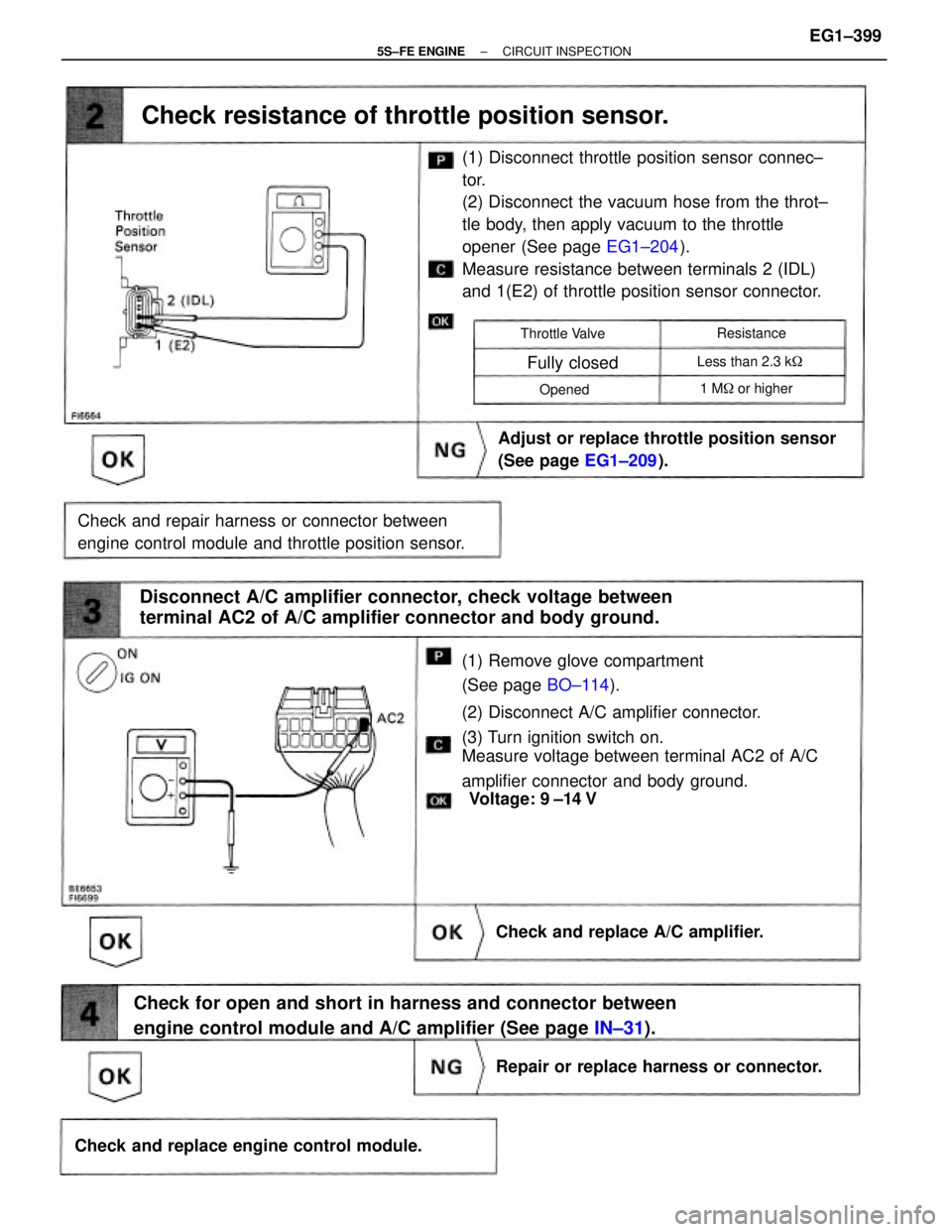
(1) Remove glove compartment
(See page BO±114).
(2) Disconnect A/C amplifier connector.
(3) Turn ignition switch on.
Measure voltage between terminal AC2 of A/C
amplifier connector and body ground.(1) Disconnect throttle position sensor connec±
tor.
(2) Disconnect the vacuum hose from the throt±
tle body, then apply vacuum to the throttle
opener (See page EG1±204).
Measure resistance between terminals 2 (IDL)
and 1(E2) of throttle position sensor connector.
Check for open and short in harness and connector between
engine control module and A/C amplifier (See page IN±31). Disconnect A/C amplifier connector, check voltage between
terminal AC2 of A/C amplifier connector and body ground.
Check and repair harness or connector between
engine control module and throttle position sensor.Adjust or replace throttle position sensor
(See page EG1±209).
Check resistance of throttle position sensor.
Check and replace engine control module.Repair or replace harness or connector. Check and replace A/C amplifier.
1 M� or higher Less than 2.3 k� Throttle Valve
Fully closed
Resistance
Opened
Voltage: 9 ±14 V
± 5S±FE ENGINECIRCUIT INSPECTIONEG1±399
Page 474 of 4770
CIRCUIT DESCRIPTION
VSV Circuit for Fuel Pressure Control (Only for California
spec.)
Check for open and short in harness and
connector between EFI main relay and ECM.Proceed to next circuit inspection
shown on matrix chart
(See page EG1±327).
Repair or replace harness or connector. Check voltage of VSV power source. Check VSV for fuel pressure control.
Check and replace ECM.Replace VSV.
DIAGNOSTIC CHART
The ECM turns on a VSV (Vacuum Switching
Valve) to draw the air into the diaphragm chamber
of the pressure regulator if it detects that the tem-
perature of the engine coolant is too high during
engine starting. The air drawn into the chamber
increases the fuel pressure to prevent fuel vapor
lock at high engine temperature in order to help the
engine start when it is warm.
Fuel pressure control ends approx. 90 secs. after
the engine is started.
± 5S±FE ENGINECIRCUIT INSPECTIONEG1±424
Page 790 of 4770

'99camry U
24
The indicator lamp goes off after driving
several times. If the indicator lamp does
not go off, contact your Toyota dealer as
soon as possible.
CAUTION
�Make sure the cap is tightened se-
curely to prevent fuel spillage in
case of an accident.
�Use only a genuine Toyota fuel tank
cap for replacement. It has a built±
in check valve to reduce fuel tank
vacuum.
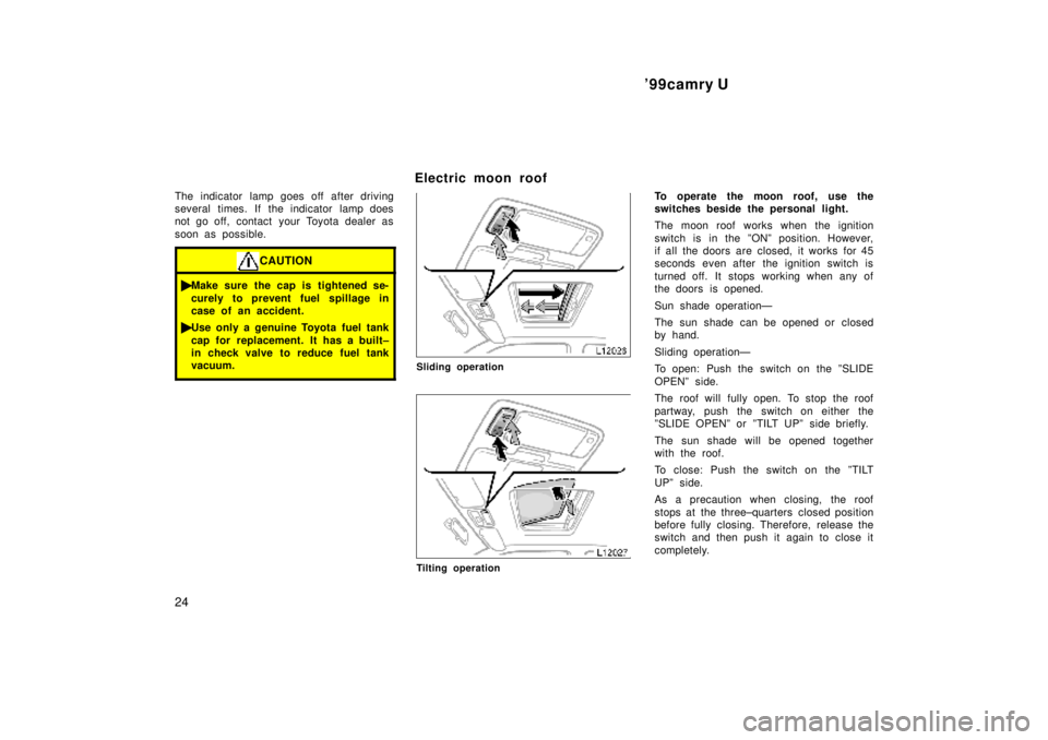
Electric moon roof
Sliding operation
Tilting operation
To operate the moon roof, use the
switches beside the personal light.
The moon roof works when the ignition
switch is in the ºONº position. However,
if all the doors are closed, it works for 45
seconds even after the ignition switch is
turned off. It stops working when any of
the doors is opened.
Sun shade operationÐ
The sun shade can be opened or closed
by hand.
Sliding operationÐ
To open: Push the switch on the ºSLIDE
OPENº side.
The roof will fully open. To stop the roof
partway, push the switch on either the
ºSLIDE OPENº or ºTILT UPº side briefly.
The sun shade will be opened together
with the roof.
To close: Push the switch on the ºTILT
UPº side.
As a precaution when closing, the roof
stops at the three±quarters closed position
before fully closing. Therefore, release the
switch and then push it again to close it
completely.
Page 1164 of 4770
* The titles given inside the components are the names of the terminals (terminal codes) and are not treated as being
abbreviations.
ABBREVIATIONS D
ABBREVIATIONS
The following abbreviations are used in this manual.
ABS = Anti±Lock Brake System
A/C = Air Conditioning
ACIS = Acoustic Control Induction System
A/T = Automatic Transaxle
COMB. = Combination
ECU = Electronic Control Unit
EGR = Exhaust Gas Recirculation
ESA = Electronic Spark Advance
EVAP = Evaporative Emission
FL = Fusible Link
J/B = Junction Block
LH = Left±Hand
M/T = Manual Transaxle
O/D = Overdrive
R/B = Relay Block
RH = Right±Hand
SFI = Sequential Multiport Fuel Injection
SRS = Supplemental Restraint System
SW = Switch
TEMP. = Temperature
VSV = Vacuum Switching Valve
w/ = With
w/o = Without