Page 3385 of 4770
EC0AW±01
S05477
DisconnectOhmmeter
E2 VC
B01480
E2(±)
VC(+)
± EMISSION CONTROL (1MZ±FE)EXHAUST GAS RECIRCULATION (EGR) SYSTEM
EC±11
1426 Author�: Date�:
EXHAUST GAS RECIRCULATION
(EGR) SYSTEM
INSPECTION
1. INSPECT EGR SYSTEM (See page DI±358)
2. INSPECT EGR VALVE POSITION SENSOR
(a) Inspect the resistance of the EGR valve position sensor.
(1) Disconnect the EGR valve position sensor connec-
tor.
(2) Using an ohmmeter, measure the resistance be-
tween the terminals VC and E2.
Resistance: 1.5 ± 4.3 kW
If the resistance is not as specified, replace the EGR valve posi-
tion sensor.
(3) Reconnect the EGR valve position sensor connec-
tor.
(b) Inspect the power output voltage of the EGR valve posi-
tion sensor.
(1) Disconnect the vacuum hose from the EGR valve.
(2) Turn the ignition switch ON.
(3) Connect a voltmeter to terminals VC and E2 of the
ECM, and measure the power source voltage.
Voltage: 4.5 ± 5.5 V
Page 3402 of 4770

EM081±05
S05331
EM±10
± ENGINE MECHANICAL (5S±FE)IDLE SPEED
1182 Author�: Date�:
IDLE SPEED
INSPECTION
1. INITIAL CONDITIONS
(a) Engine at normal operating temperature
(b) Air cleaner installed
(c) All pipes and hoses of air induction system connected
(d) All vacuum lines properly connected
(e) SFI system wiring connectors fully plugged
(f) All operating accessories switched OFF
(g) Ignition timing check correctly
(h) Transmission in neutral position
(i) Air conditioning switched OFF
2. CONNECT TOYOTA HAND±HELD TESTER OR OBDII
SCAN TOOL
(a) Remove the fuse cover on the instrument panel.
(b) Connect a TOYOTA hand±held tester or OBDII scan tool
to the DLC3.
(c) Please refer to the TOYOTA hand±held tester or OBDII
scan tool operator's manual for further details.
3. INSPECT IDLE SPEED
(a) Race the engine at 2,500 rpm for approx. 90 seconds.
(b) Check the idle speed.
Idle speed (w/ Cooling fan OFF): 700 ± 50 rpm
If the idle speed is not as specified, check the IAC valve and air
intake system.
4. DISCONNECT TOYOTA HAND±HELD TESTER OR
OBDII SCAN TOOL
Page 3426 of 4770

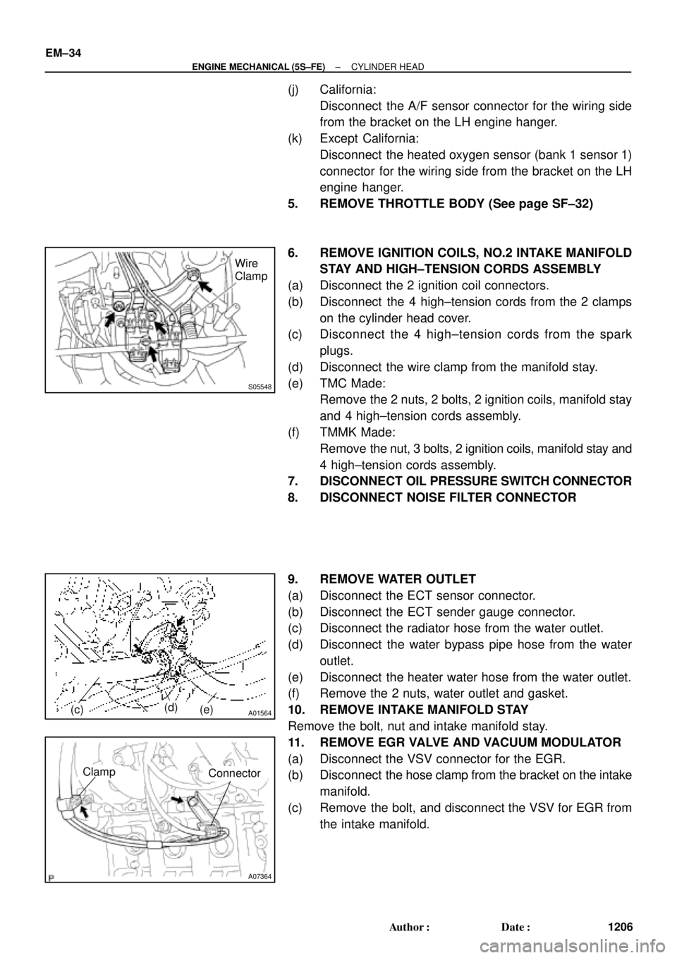
S05548
Wire
Clamp
A01564(c)(d)
(e)
A07364
ConnectorClamp
EM±34
± ENGINE MECHANICAL (5S±FE)CYLINDER HEAD
1206 Author�: Date�:
(j) California:
Disconnect the A/F sensor connector for the wiring side
from the bracket on the LH engine hanger.
(k) Except California:
Disconnect the heated oxygen sensor (bank 1 sensor 1)
connector for the wiring side from the bracket on the LH
engine hanger.
5. REMOVE THROTTLE BODY (See page SF±32)
6. REMOVE IGNITION COILS, NO.2 INTAKE MANIFOLD
STAY AND HIGH±TENSION CORDS ASSEMBLY
(a) Disconnect the 2 ignition coil connectors.
(b) Disconnect the 4 high±tension cords from the 2 clamps
on the cylinder head cover.
(c) Disconnect the 4 high±tension cords from the spark
plugs.
(d) Disconnect the wire clamp from the manifold stay.
(e) TMC Made:
Remove the 2 nuts, 2 bolts, 2 ignition coils, manifold stay
and 4 high±tension cords assembly.
(f) TMMK Made:
Remove the nut, 3 bolts, 2 ignition coils, manifold stay and
4 high±tension cords assembly.
7. DISCONNECT OIL PRESSURE SWITCH CONNECTOR
8. DISCONNECT NOISE FILTER CONNECTOR
9. REMOVE WATER OUTLET
(a) Disconnect the ECT sensor connector.
(b) Disconnect the ECT sender gauge connector.
(c) Disconnect the radiator hose from the water outlet.
(d) Disconnect the water bypass pipe hose from the water
outlet.
(e) Disconnect the heater water hose from the water outlet.
(f) Remove the 2 nuts, water outlet and gasket.
10. REMOVE INTAKE MANIFOLD STAY
Remove the bolt, nut and intake manifold stay.
11. REMOVE EGR VALVE AND VACUUM MODULATOR
(a) Disconnect the VSV connector for the EGR.
(b) Disconnect the hose clamp from the bracket on the intake
manifold.
(c) Remove the bolt, and disconnect the VSV for EGR from
the intake manifold.
Page 3453 of 4770

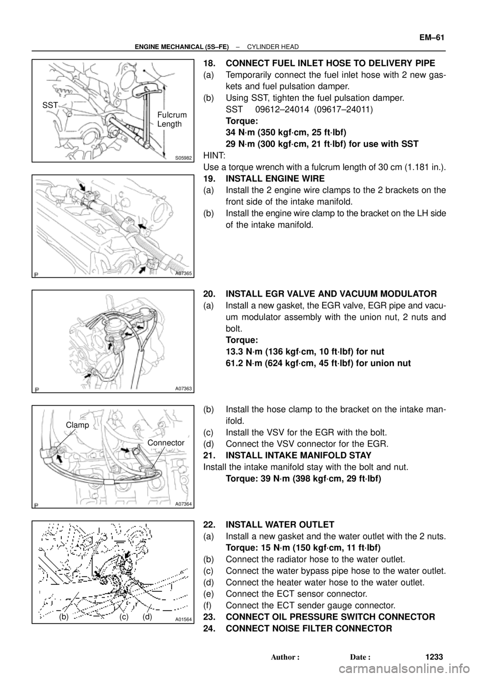
S05982
SST
Fulcrum
Length
A07365
A07363
A07364
Clamp
Connector
A01564(b)(c)(d)
± ENGINE MECHANICAL (5S±FE)CYLINDER HEAD
EM±61
1233 Author�: Date�:
18. CONNECT FUEL INLET HOSE TO DELIVERY PIPE
(a) Temporarily connect the fuel inlet hose with 2 new gas-
kets and fuel pulsation damper.
(b) Using SST, tighten the fuel pulsation damper.
SST 09612±24014 (09617±24011)
Torque:
34 N´m (350 kgf´cm, 25 ft´lbf)
29 N´m (300 kgf´cm, 21 ft´lbf) for use with SST
HINT:
Use a torque wrench with a fulcrum length of 30 cm (1.181 in.).
19. INSTALL ENGINE WIRE
(a) Install the 2 engine wire clamps to the 2 brackets on the
front side of the intake manifold.
(b) Install the engine wire clamp to the bracket on the LH side
of the intake manifold.
20. INSTALL EGR VALVE AND VACUUM MODULATOR
(a) Install a new gasket, the EGR valve, EGR pipe and vacu-
um modulator assembly with the union nut, 2 nuts and
bolt.
Torque:
13.3 N´m (136 kgf´cm, 10 ft´lbf) for nut
61.2 N´m (624 kgf´cm, 45 ft´lbf) for union nut
(b) Install the hose clamp to the bracket on the intake man-
ifold.
(c) Install the VSV for the EGR with the bolt.
(d) Connect the VSV connector for the EGR.
21. INSTALL INTAKE MANIFOLD STAY
Install the intake manifold stay with the bolt and nut.
Torque: 39 N´m (398 kgf´cm, 29 ft´lbf)
22. INSTALL WATER OUTLET
(a) Install a new gasket and the water outlet with the 2 nuts.
Torque: 15 N´m (150 kgf´cm, 11 ft´lbf)
(b) Connect the radiator hose to the water outlet.
(c) Connect the water bypass pipe hose to the water outlet.
(d) Connect the heater water hose to the water outlet.
(e) Connect the ECT sensor connector.
(f) Connect the ECT sender gauge connector.
23. CONNECT OIL PRESSURE SWITCH CONNECTOR
24. CONNECT NOISE FILTER CONNECTOR
Page 3518 of 4770
EM0YN±01
EM±12
± ENGINE MECHANICAL (1MZ±FE)IDLE SPEED
1298 Author�: Date�:
IDLE SPEED
INSPECTION
1. INITIAL CONDITIONS
(a) Engine at normal operating temperature
(b) Air cleaner installed
(c) All pipes and hoses of air induction system connected
(d) All accessories switched OFF
(e) All vacuum lines properly connected
HINT:
All vacuum hoses for EGR system, etc. should be properly connected.
(f) SFI system wiring connectors fully plugged
(g) Ignition timing check correctly
(h) Transmission in neutral position
2. CONNECT TOYOTA HAND±HELD TESTER OR OBDII SCAN TOOL (See page EM±10)
3. INSPECT IDLE SPEED
(a) Race the engine speed at 2,500 rpm for approx. 90 seconds.
(b) Check the idle speed.
Idle speed: 700 ± 50 rpm
If the idle speed is not as specified, check the IAC valve and air intake system.
4. DISCONNECT TOYOTA HAND±HELD TESTER OR OBDII SCAN TOOL
Page 3707 of 4770

IN04Q±03
IN±36
± INTRODUCTIONTERMS
36 Author�: Date�:
TERMS
ABBREVIATIONS USED IN THIS MANUAL
AbbreviationsMeaning
ABSAnti±Lock Brake System
ACAlternating Current
ACCAccessory
ACISAcoustic Control Induction System
ACSDAutomatic Cold Start Device
A.D.D.Automatic Disconnecting Differential
A/FAir±Fuel Ratio
AHCActive Height Control Suspension
ALRAutomatic Locking Retractor
ALTAlternator
AMPAmplifier
ANTAntenna
APPROX.Approximately
A/TAutomatic Transmission (Transaxle)
AT FAutomatic Transmission Fluid
AUTOAutomatic
AUXAuxiliary
AV GAverage
AV SAdaptive Variable Suspension
BACSBoost Altitude Compensation System
BATBattery
BDCBottom Dead Center
B/LBi±Level
B/SBore±Stroke Ratio
BTDCBefore Top Dead Center
BVSVBimetallic Vacuum Switching Valve
Calif.California
CBCircuit Breaker
CCoCatalytic Converter For Oxidation
CDCompact Disc
CFCornering Force
CGCenter Of Gravity
CHChannel
COMB.Combination
CPECoupe
CPSCombustion Pressure Sensor
CPUCentral Processing Unit
CRSChild Restraint System
CTRCenter
C/VCheck Valve
CVControl Valve
CWCurb Weight
Page 3711 of 4770
IN±40
± INTRODUCTIONTERMS
40 Author�: Date�:
TISTotal Information System For Vehicle Development
T/MTransmission
TMCTOYOTA Motor Corporation
TMMKTOYOTA Motor Manufacturing Kentucky, Inc.
TRACTraction Control System
TURBOTurbocharge
U/DUnderdrive
U/SUndersize
VCVVacuum Control Valve
VENTVentilator
VINVehicle Identification Number
VPSVariable Power Steering
VSCVehicle Skid Control Vehicle Stability Control
VSVVacuum Switching Valve
VTVVacuum Transmitting Valve
w/With
WGNWagon
W/HWire Harness
w/oWithout
1stFirst
2ndSecond
2WDTwo Wheel Drive Vehicle (4x2)
4WDFour Wheel Drive Vehicle (4x4)
Page 3714 of 4770
± INTRODUCTIONTERMS
IN±43
43 Author�: Date�:
TCMTransmission Control ModuleTransmission ECU, ECT ECU
TPThrottle PositionThrottle Position
TRTransmission Range±
TVVThermal Vacuum ValveBimetallic Vacuum Switching Valve (BVSV)
Thermostatic Vacuum Switching Valve (TVSV)
TWCThree±Way Catalytic Converter
Three±Way Catalytic (TWC)
Manifold Converter
CC
RO
TWC+OCThree±Way + Oxidation Catalytic ConverterCCR + CCo
VA FVolume Air FlowAir Flow Meter
VRVoltage RegulatorVoltage Regulator
VSSVehicle Speed SensorVehicle Speed Sensor
WOTWide Open ThrottleFull Throttle
WU±OCWarm Up Oxidation Catalytic Converter±
WU±TWCWarm Up Three±Way Catalytic Converter±
3GRThird Gear±
4GRFourth Gear±