Page 350 of 4770

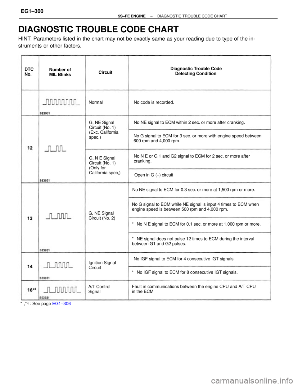
DIAGNOSTIC TROUBLE CODE CHART
HINT: Parameters listed in the chart may not be exactly same as your reading due to type of the in-
struments or other factors.
No G signal to ECM while NE signal is input 4 times to ECM when
engine speed is between 500 rpm and 4,000 rpm.No G signal to ECM for 3 sec. or more with engine speed between
600 rpm and 4,000 rpm.
*� NE signal does not pulse 12 times to ECM during the interval
between G1 and G2 pulses.
Fault in communications between the engine CPU and A/T CPU
in the ECMNo N E or G 1 and G2 signal to ECM for 2 sec. or more after
cranking.
*� No N E signal to ECM for 0.1 sec. or more at 1,000 rpm or more. No NE signal to ECM for 0.3 sec. or more at 1,500 rpm or more.No NE signal to ECM within 2 sec. or more after cranking.
*� No IGF signal to ECM for 8 consecutive IGT signals. No IGF signal to ECM for 4 consecutive IGT signals. G, N E Signal
Circuit (No. 1)
(Only for
California spec,) G, NE Signal
Circuit (No. 1)
(Exc. California
spec.)Diagnostic Trouble Code
Detecting Condition
G, NE Signal
Circuit (No. 2)
Ignition Signal
Circuit
*�,*� : See page EG1±306A/T Control
SignalOpen in G (±) circuit Number of
MIL Blinks
No code is recorded. DTC
No.Circuit
Normal
± 5S±FE ENGINEDIAGNOSTIC TROUBLE CODE CHARTEG1±300
Page 358 of 4770

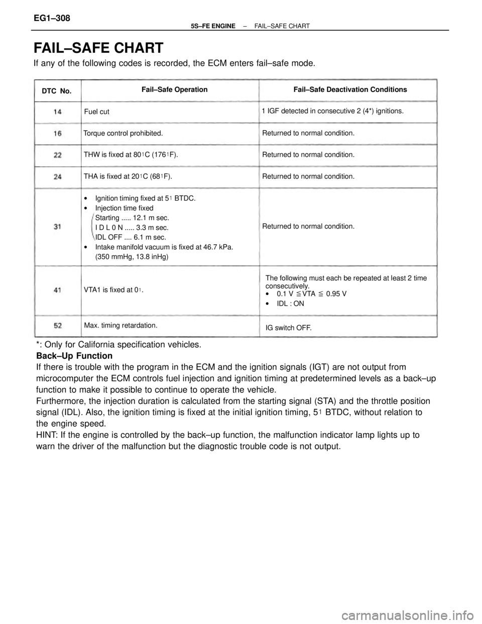
*: Only for California specification vehicles.
Back±Up Function
If there is trouble with the program in the ECM and the ignition signals (IGT) are not output from
microcomputer the ECM controls fuel injection and ignition timing at predetermined levels as a back±up
function to make it possible to continue to operate the vehicle.
Furthermore, the injection duration is calculated from the starting signal (STA) and the throttle position
signal (IDL). Also, the ignition timing is fixed at the initial ignition timing, 5� BTDC, without relation to
the engine speed.
HINT: If the engine is controlled by the back±up function, the malfunction indicator lamp lights up to
warn the driver of the malfunction but the diagnostic trouble code is not output.
FAIL±SAFE CHART
If any of the following codes is recorded, the ECM enters fail±safe mode.
wIgnition timing fixed at 5� BTDC.
wInjection time fixed
Starting ..... 12.1 m sec.
I D L 0 N ..... 3.3 m sec.
IDL OFF .... 6.1 m sec.
wIntake manifold vacuum is fixed at 46.7 kPa.
(350 mmHg, 13.8 inHg)
The following must each be repeated at least 2 time
consecutively.
w0.1 V �VTA � 0.95 V
wIDL : ON 1 IGF detected in consecutive 2 (4*) ignitions.Fail±Safe Deactivation Conditions
THW is fixed at 80�C (176�F).
THA is fixed at 20�C (68�F). Returned to normal condition.Returned to normal condition.
Returned to normal condition. Returned to normal condition. Torque control prohibited.
Max. timing retardation.Fail±Safe Operation
VTA1 is fixed at 0
�.
IG switch OFF. DTC No.
Fuel cut
± 5S±FE ENGINEFAIL±SAFE CHARTEG1±308
Page 371 of 4770
*�: Only for California specification vehicles.
*�: Except California specification vehicles with A/T.wStoplight switch
w Stoplight
w Park/neutral position switch wDefogger relay
wTaillight relay
Park/neutral position switchPark/neutral position switch
Park/neutral position switch
Malfunction indicator lampData link connector 1 and 2 Data link connector 1 and 2No.1 vehicle speed sensor
Throttle position sensor
Throttle position sensorEGR gas temp. sensor
Circuit opening relay Data link connector 1Data link connector 2
Cruise control ECUO/D main switch Terminal
No.Terminal
No.Connection
A/C amplifier
EFI main relay Sensor ground
Sensor ground
A/C amplifierEFI main relay
Knock sensorStarter relay Connection Symbol
Symbol
Battery
± 5S±FE ENGINETERMINALS OF ECMEG1±321
Page 394 of 4770

CIRCUIT DESCRIPTION
The ECM determines the ignition timing, turns on Tr, at a predetermined angle ('*CA) before the
desired ignition timing and outputs an ignition signal (IGT) ª1º to the igniter.
Since the width of the IGT signal is constant, the dwell angle control circuit in the igniter determines
the time the control circuit starts primary current flow to the ignition coil based on the engine rpm and
ignition timing one revolution ago, that is, the time the Tr
2 turns on.
When it reaches the ignition timing, the ECM turns Tr, off and outputs the IGT signal ªOº.
This turns Tr2 off, interrupting the primary current flow and generating a high voltage in the secondary
coil which causes the spark plug to spark. Also, by the counter electromotive force generated when
the primary current is interrupted, the igniter sends an ignition confirmation signal (IGF) to the ECM.
The ECM stops fuel injection as a fail safe function when the lG F signal is not input to the ECM.
wOpen or short in IG F or IGT circuit from
igniter to ECM.
wIgniter
wECM No IGF signal to ECM for 4 (8*2) consecutive
IGT signals. Diagnostic Trouble Code Detecting Condition
WIRING DIAGRAM
Trouble Area
DTC 14 Ignition Signal Circuit
DTC No.
± 5S±FE ENGINECIRCUIT INSPECTIONEG1±344
Page 432 of 4770
(1) Remove glove compartment.
(See page EG1±234).
(2) Disconnect cruise control ECU connector.
(3) Shift the shift lever to N position or neutral.
(4) Jack up a front wheel on one side.
(5) Turn ignition switch on. Drive the vehicle and check if the operation of the speedometer in the combination meter is
normal.
The No. 1 vehicle speed sensor is operating normally if the speedometer display is normal.
Check voltage between terminal SPD of engine control module
connector and body ground.
Check speedometer circuit. See combination
meter troubleshooting on page BE±66.
Check speedometer circuit. See combination
meter troubleshooting on page BE±66.
Check operation of speedometer.
Check and replace engine control module.
INSPECTION PROCEDURE
Measure voltage between terminal SPD of
engine control module connector and body
ground when the wheel is turned slowly.
Voltage is generated intermittently.
± 5S±FE ENGINECIRCUIT INSPECTIONEG1±382
Page 450 of 4770

CIRCUIT DESCRIPTION
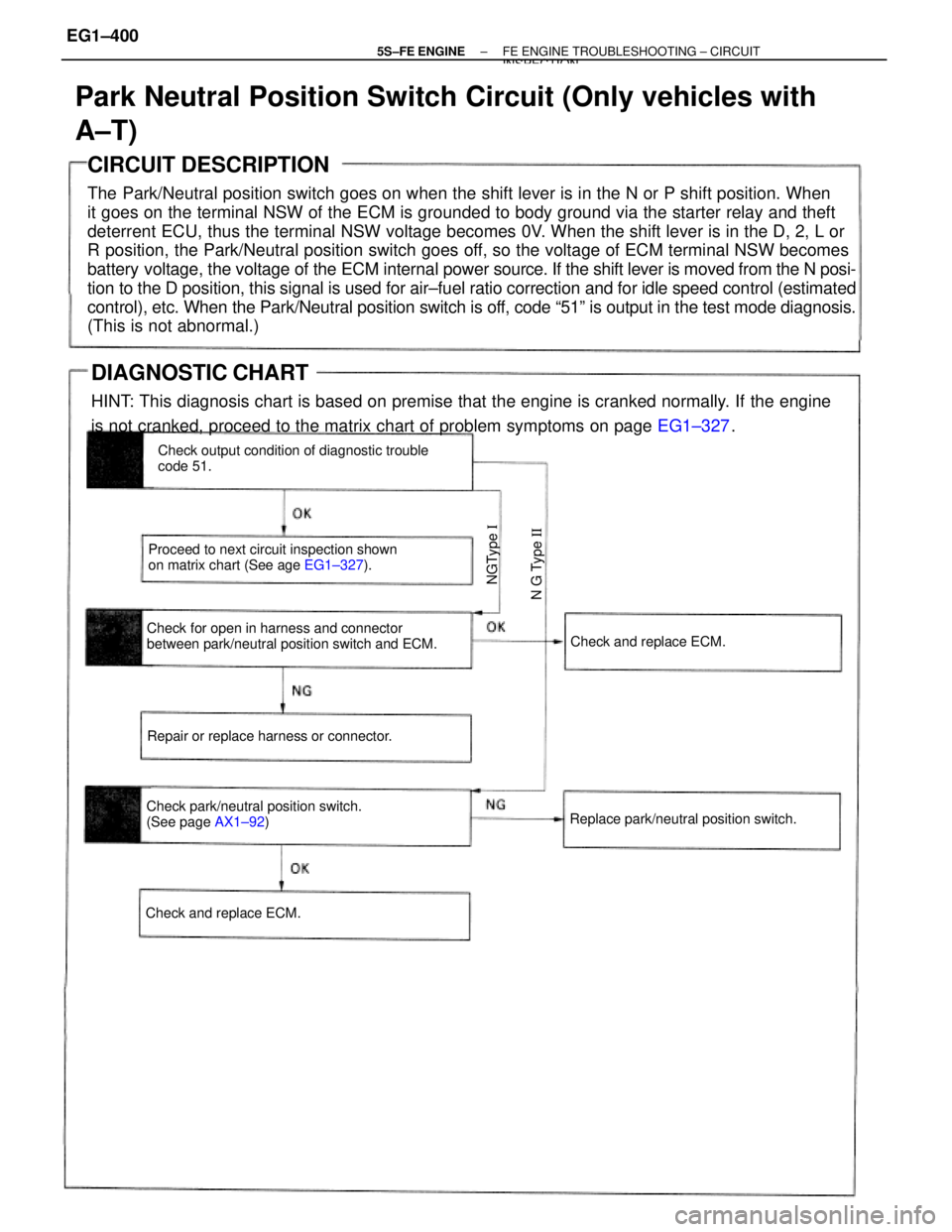
The Park/Neutral position switch goes on when the shift lever is in the N or P shift position. When
it goes on the terminal NSW of the ECM is grounded to body ground via the starter relay and theft
deterrent ECU, thus the terminal NSW voltage becomes 0V. When the shift lever is in the D, 2, L or
R position, the Park/Neutral position switch goes off, so the voltage of ECM terminal NSW becomes
battery voltage, the voltage of the ECM internal power source. If the shift lever is moved from the N posi-
tion to the D position, this signal is used for air±fuel ratio correction and for idle speed control (estimated
control), etc. When the Park/Neutral position switch is off, code ª51º is output in the test mode diagnosis.
(This is not abnormal.)
Park Neutral Position Switch Circuit (Only vehicles with
A±T)
Check for open in harness and connector
between park/neutral position switch and ECM.Check output condition of diagnostic trouble
code 51.
Proceed to next circuit inspection shown
on matrix chart (See age EG1±327).
Check park/neutral position switch.
(See page AX1±92) Repair or replace harness or connector.
Replace park/neutral position switch.Check and replace ECM.
Check and replace ECM.
N G Type II NGType I
DIAGNOSTIC CHART
HINT: This diagnosis chart is based on premise that the engine is cranked normally. If the engine
is not cranked, proceed to the matrix chart of problem symptoms on page EG1±327.
± 5S±FE ENGINEFE ENGINE TROUBLESHOOTING ± CIRCUITINSPECTION
EG1±400
Page 458 of 4770
CIRCUIT DESCRIPTION
Battery positive voltage is supplied to terminal BATT of the ECM even when the ignition switch is off
for use by the diagnostic trouble code memory and air±fuel ratio adaptive control value memory, etc.
Back Up Power Source Circuit
Proceed to next circuit inspection
shown on matrix chart (See page EG1±327).Check and repair harness or connector
between battery, EFI fuse and ECU. Check for short in all the harness and
components connected to EFI fuse.
DIAGNOSTIC CHART
Check operation for the back up. Check voltage of terminal6ATT.
WIRING DIAGRAM
Check and replace ECM. Check EFI fuse.
± 5S±FE ENGINECIRCUIT INSPECTIONEG1±408
Page 504 of 4770

23
INTERIOR
� WIRELESS DOOR LOCK REMOTE CONTROL SYSTEM
�A wireless door lock remote control system is available as an option on the LE grade model and is standard
equipment on the XLE grade model. With the wireless door lock remote control system, all the doors can be locked
and unlocked by signals emitted by the transmitter.
�A 2±step unlock function is provided. When the unlock switch of the transmitter is pressed once, only the driver's
door is unlocked. When it is pressed twice, all the doors are unlocked.
�A panic switch is provided in the transmitter to force the theft system by operating the horn, headlight and taillight.
�A wireless door lock ECU with EEPROM (Electrical Erasable Programmable ROM) is used so that the transmitter
recognition code can be easily reprogrammed.
� THEFT DETERRENT SYSTEM
�A theft deterrent system is used to prevent vehicle theft. When the system is set, the horn and headlights operate
if the door, hood or trunk is forcibly opened.
�The audio system also has an anti±theft system whereby the radio and cassette deck is disabled if the radio body
is stolen from the vehicle.