Page 495 of 4770
14
EXTERIOR
2. Rear Lights
�The rear combination light has adopted a
construction in which the light extends to the end
of the lens. Thus, as a result of expanding the
effective luminance area, the visibility from
other vehicles has been improved.
�The light diffusion characteristic of the back±up
light has been revised to improve further
visibility when backing up at night.
� MOON ROOF
A power tilt±up and sliding moon roof is optional equipment for LE and XLE grade models. A one±touch slide±open
function is added.
� WINDSHIELD GLASS AND WINDOW GLASS
The front windshield, the rear window, and all door windows use the type of glass that dramatically shuts out ultraviolet
and infrared rays. As a result, sunburns from ultraviolet rays and heat from infrared rays have been reduced and reduction
of heat load to the air conditioning system.
Page 506 of 4770
25
INTERIOR
� INNER REAR VIEW MIRROR
The inner rear view mirror is the type that is
mounted on the inside of the front windshield glass.
� OVERHEAD CONSOLE
�An overhead console is provided in front of the map lamp to store a garage door opener transmitter. This console
is constructed to enable the operation of a transmitter in its stored state.
�Also, by changing its cover, the console can be used to store a pair of sunglasses.
� SUN VISOR
Extension plates have been added to reduce glare
coming into the vehicle from the side.
Page 1970 of 4770
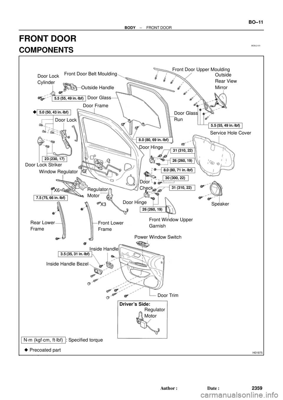
BO0L2±01
H01975
Door Lock
Cylinder
Outside Handle Front Door Belt Moulding
Door Glass
Door FrameFront Door Upper Moulding
Outside
Rear View
Mirror
Door Glass
Run
5.5 (55, 49 in.´lbf)
5.5 (55, 49 in.´lbf)
5.0 (50, 43 in.´lbf)�
Door Lock
23 (230, 17)
Window Regulator
8.0 (80, 69 in.´lbf)
Door Hinge
X6
7.5 (75, 66 in.´lbf)
Regulator
Motor
X3
31 (310, 22)
26 (260, 19)
8.0 (80, 71 in.´lbf)
30 (300, 22)
31 (310, 22)
Door
Check
Door Hinge
26 (260, 19)
Speaker
Power Window Switch Rear Lower
FrameFront Lower
FrameFront Window Upper
Garnish
Inside Handle Bezel
3.5 (35, 31 in.´lbf)
Driver's Side:
Regulator
Motor
Ptdt
N´m (kgf´cm, ft´lbf) : Specified torqueInside Handle
Door Trim
� Precoated part Door Lock StrikerService Hole Cover
± BODYFRONT DOOR
BO±11
2359 Author�: Date�:
FRONT DOOR
COMPONENTS
Page 1972 of 4770
N20970
(a)
(b)(b)
N21004
Clip
H01729
: 7 rivets
: clip
: clip
: clip
± BODYFRONT DOOR
BO±13
2361 Author�: Date�:
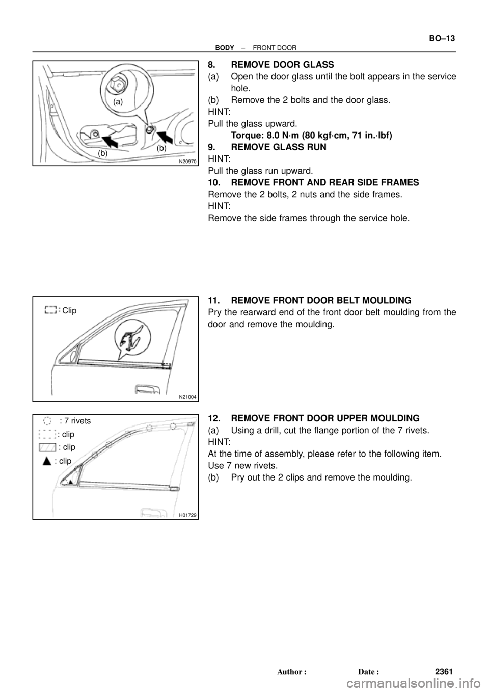
8. REMOVE DOOR GLASS
(a) Open the door glass until the bolt appears in the service
hole.
(b) Remove the 2 bolts and the door glass.
HINT:
Pull the glass upward.
Torque: 8.0 N´m (80 kgf´cm, 71 in.´lbf)
9. REMOVE GLASS RUN
HINT:
Pull the glass run upward.
10. REMOVE FRONT AND REAR SIDE FRAMES
Remove the 2 bolts, 2 nuts and the side frames.
HINT:
Remove the side frames through the service hole.
11. REMOVE FRONT DOOR BELT MOULDING
Pry the rearward end of the front door belt moulding from the
door and remove the moulding.
12. REMOVE FRONT DOOR UPPER MOULDING
(a) Using a drill, cut the flange portion of the 7 rivets.
HINT:
At the time of assembly, please refer to the following item.
Use 7 new rivets.
(b) Pry out the 2 clips and remove the moulding.
Page 1976 of 4770
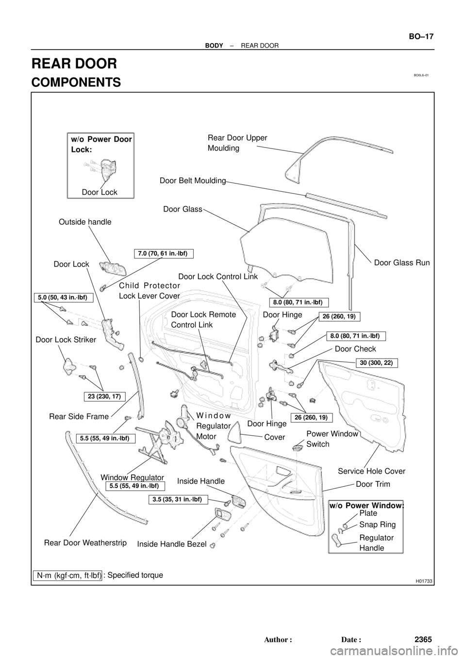
BO0L6±01
H01733
Door LockRear Door Upper
Moulding
Door Belt Moulding
Door Glass
Outside handle
Door Glass Run
Door Lock
Door Lock Striker
Rear Side Frame
Rear Door WeatherstripWindow Regulator
Inside Handle BezelInside HandleWindow
Regulator
Motor Child Protector
Lock Lever Cover
Snap Ring
Regulator
Handle Plate Door Trim Service Hole Cover Power Window
Switch Cover Door HingeDoor Hinge
Door Check w/o Power Door
Lock:
w/o Power Window:
: Specified torque
N´m (kgf´cm, ft´lbf)
3.5 (35, 31 in.´lbf)
5.5 (55, 49 in.´lbf)
5.5 (55, 49 in.´lbf)
23 (230, 17)
7.0 (70, 61 in.´lbf)
Door Lock Control Link
Door Lock Remote
Control Link
5.0 (50, 43 in.´lbf)
8.0 (80, 71 in.´lbf)
26 (260, 19)
8.0 (80, 71 in.´lbf)
30 (300, 22)
26 (260, 19)
± BODYREAR DOOR
BO±17
2365 Author�: Date�:
REAR DOOR
COMPONENTS
Page 1978 of 4770
N20974
(b)(b)
(a)
N21008
Clip
H01743
: 7 rivets
: clips
: clips
: clips
± BODYREAR DOOR
BO±19
2367 Author�: Date�:
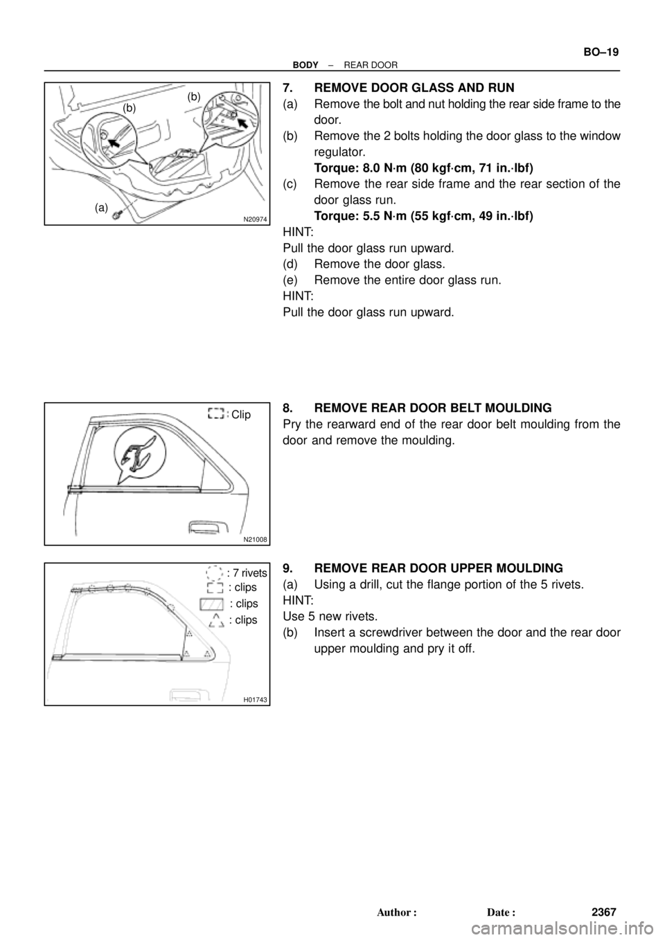
7. REMOVE DOOR GLASS AND RUN
(a) Remove the bolt and nut holding the rear side frame to the
door.
(b) Remove the 2 bolts holding the door glass to the window
regulator.
Torque: 8.0 N´m (80 kgf´cm, 71 in.´lbf)
(c) Remove the rear side frame and the rear section of the
door glass run.
Torque: 5.5 N´m (55 kgf´cm, 49 in.´lbf)
HINT:
Pull the door glass run upward.
(d) Remove the door glass.
(e) Remove the entire door glass run.
HINT:
Pull the door glass run upward.
8. REMOVE REAR DOOR BELT MOULDING
Pry the rearward end of the rear door belt moulding from the
door and remove the moulding.
9. REMOVE REAR DOOR UPPER MOULDING
(a) Using a drill, cut the flange portion of the 5 rivets.
HINT:
Use 5 new rivets.
(b) Insert a screwdriver between the door and the rear door
upper moulding and pry it off.
Page 1983 of 4770
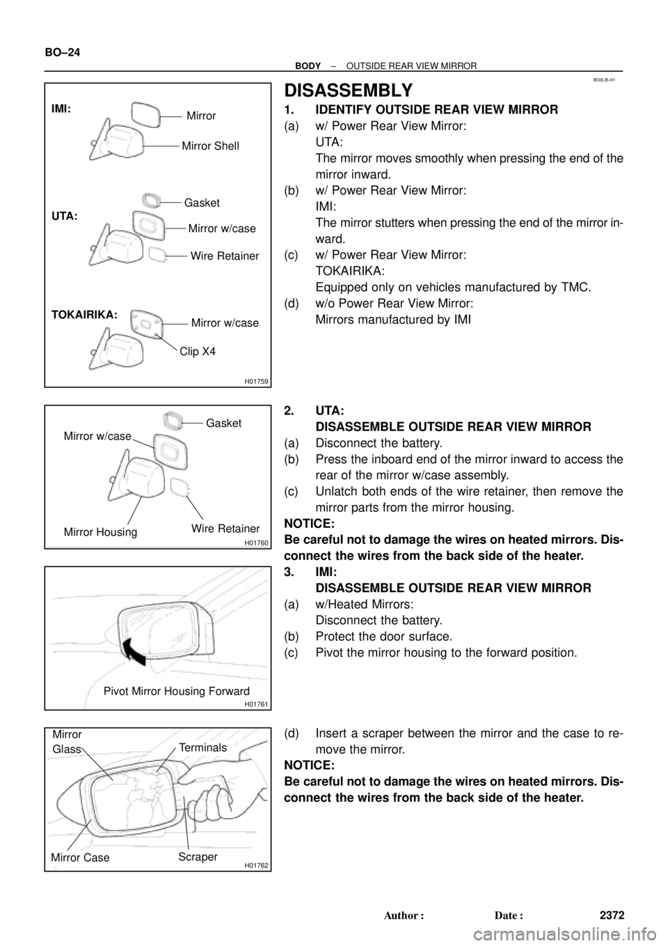
H01759
UTA: IMI:
TOKAIRIKA:
Mirror
Mirror Shell
Gasket
Mirror w/case
Wire Retainer
Mirror w/case
Clip X4
BO0LB±01
H01760
Mirror w/caseGasket
Mirror HousingWire Retainer
H01761
Pivot Mirror Housing Forward
H01762
Mirror
Glass
Terminals
Mirror CaseScraper BO±24
± BODYOUTSIDE REAR VIEW MIRROR
2372 Author�: Date�:
DISASSEMBLY
1. IDENTIFY OUTSIDE REAR VIEW MIRROR
(a) w/ Power Rear View Mirror:
UTA:
The mirror moves smoothly when pressing the end of the
mirror inward.
(b) w/ Power Rear View Mirror:
IMI:
The mirror stutters when pressing the end of the mirror in-
ward.
(c) w/ Power Rear View Mirror:
TOKAIRIKA:
Equipped only on vehicles manufactured by TMC.
(d) w/o Power Rear View Mirror:
Mirrors manufactured by IMI
2. UTA:
DISASSEMBLE OUTSIDE REAR VIEW MIRROR
(a) Disconnect the battery.
(b) Press the inboard end of the mirror inward to access the
rear of the mirror w/case assembly.
(c) Unlatch both ends of the wire retainer, then remove the
mirror parts from the mirror housing.
NOTICE:
Be careful not to damage the wires on heated mirrors. Dis-
connect the wires from the back side of the heater.
3. IMI:
DISASSEMBLE OUTSIDE REAR VIEW MIRROR
(a) w/Heated Mirrors:
Disconnect the battery.
(b) Protect the door surface.
(c) Pivot the mirror housing to the forward position.
(d) Insert a scraper between the mirror and the case to re-
move the mirror.
NOTICE:
Be careful not to damage the wires on heated mirrors. Dis-
connect the wires from the back side of the heater.
Page 2002 of 4770
BO0LP±01
N20982
N20983
BO5232
± BODYWINDSHIELD
BO±43
2391 Author�: Date�:
REMOVAL
1. REMOVE THESE PARTS:
(a) Inner rear view mirror
(b) Sun visors and holders
(c) Map light assembly
(d) Front pillar garnishes
(e) Hood
(f) Wiper arms
(g) Cowl louvers
(h) Weatherstrips
2. REMOVE WEATHERSTRIP
Remove the weatherstrip by pulling.
HINT:
Remove only the front half of weatherstrip.
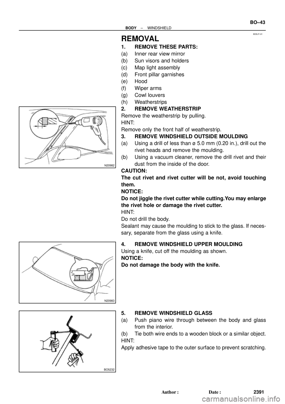
3. REMOVE WINDSHIELD OUTSIDE MOULDING
(a) Using a drill of less than ù 5.0 mm (0.20 in.), drill out the
rivet heads and remove the moulding.
(b) Using a vacuum cleaner, remove the drill rivet and their
dust from the inside of the door.
CAUTION:
The cut rivet and rivet cutter will be not, avoid touching
them.
NOTICE:
Do not jiggle the rivet cutter while cutting.You may enlarge
the rivet hole or damage the rivet cutter.
HINT:
Do not drill the body.
Sealant may cause the moulding to stick to the glass. If neces-
sary, separate from the glass using a knife.
4. REMOVE WINDSHIELD UPPER MOULDING
Using a knife, cut off the moulding as shown.
NOTICE:
Do not damage the body with the knife.
5. REMOVE WINDSHIELD GLASS
(a) Push piano wire through between the body and glass
from the interior.
(b) Tie both wire ends to a wooden block or a similar object.
HINT:
Apply adhesive tape to the outer surface to prevent scratching.