Page 2102 of 4770
BE±8
± BODY ELECTRICALBODY ELECTRICAL SYSTEM
2228 Author�: Date�:
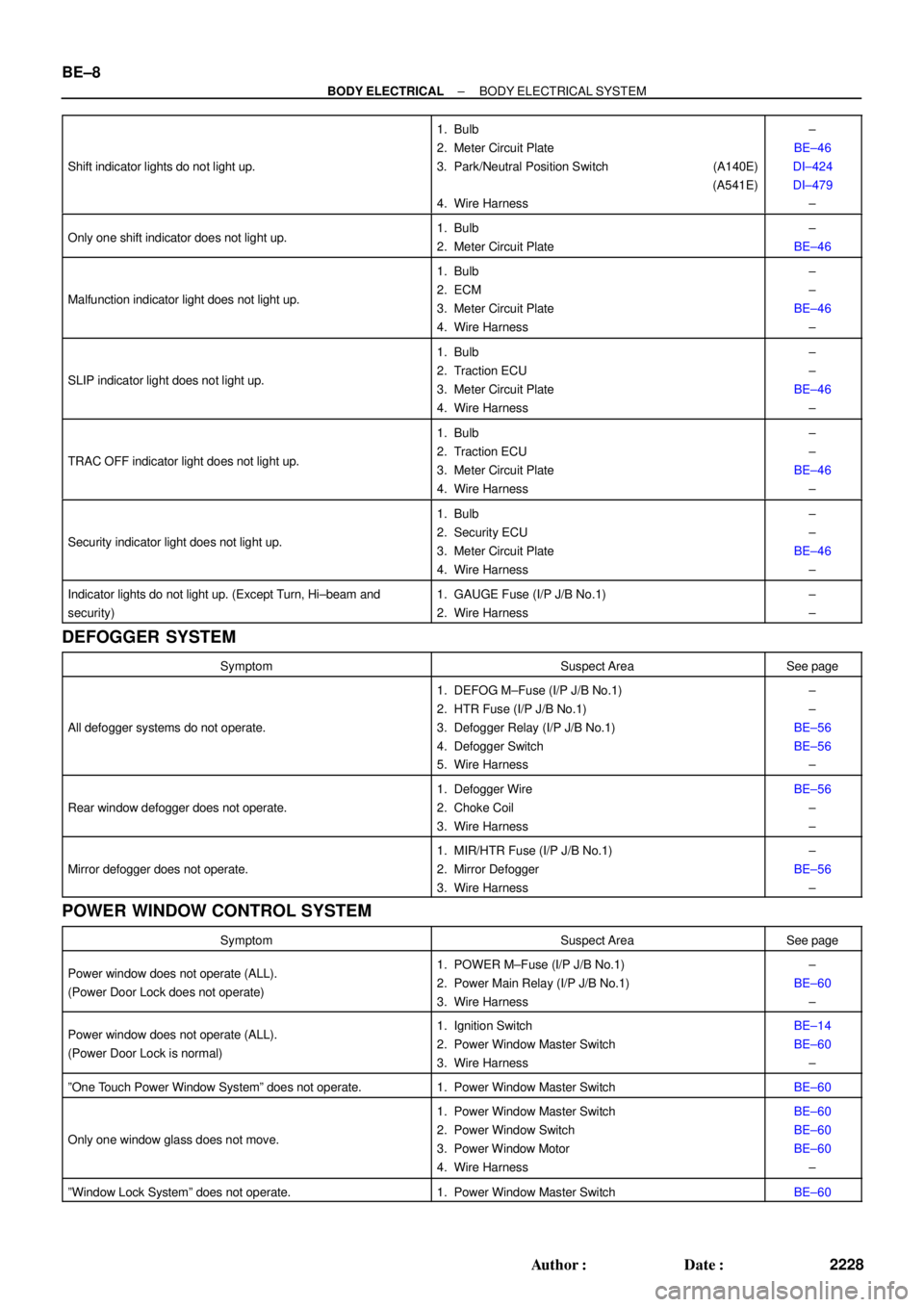
Shift indicator lights do not light up.
1. Bulb
2. Meter Circuit Plate
3. Park/Neutral Position Switch (A140E)
(A541E)
4. Wire Harness±
BE±46
DI±424
DI±479
±
Only one shift indicator does not light up.1. Bulb
2. Meter Circuit Plate±
BE±46
Malfunction indicator light does not light up.
1. Bulb
2. ECM
3. Meter Circuit Plate
4. Wire Harness±
±
BE±46
±
SLIP indicator light does not light up.
1. Bulb
2. Traction ECU
3. Meter Circuit Plate
4. Wire Harness±
±
BE±46
±
TRAC OFF indicator light does not light up.
1. Bulb
2. Traction ECU
3. Meter Circuit Plate
4. Wire Harness±
±
BE±46
±
Security indicator light does not light up.
1. Bulb
2. Security ECU
3. Meter Circuit Plate
4. Wire Harness±
±
BE±46
±
Indicator lights do not light up. (Except Turn, Hi±beam and
security)1. GAUGE Fuse (I/P J/B No.1)
2. Wire Harness±
±
DEFOGGER SYSTEM
SymptomSuspect AreaSee page
All defogger systems do not operate.
1. DEFOG M±Fuse (I/P J/B No.1)
2. HTR Fuse (I/P J/B No.1)
3. Defogger Relay (I/P J/B No.1)
4. Defogger Switch
5. Wire Harness±
±
BE±56
BE±56
±
Rear window defogger does not operate.
1. Defogger Wire
2. Choke Coil
3. Wire HarnessBE±56
±
±
Mirror defogger does not operate.
1. MIR/HTR Fuse (I/P J/B No.1)
2. Mirror Defogger
3. Wire Harness±
BE±56
±
POWER WINDOW CONTROL SYSTEM
SymptomSuspect AreaSee page
Power window does not operate (ALL).
(Power Door Lock does not operate)1. POWER M±Fuse (I/P J/B No.1)
2. Power Main Relay (I/P J/B No.1)
3. Wire Harness±
BE±60
±
Power window does not operate (ALL).
(Power Door Lock is normal)1. Ignition Switch
2. Power Window Master Switch
3. Wire HarnessBE±14
BE±60
±
ºOne Touch Power Window Systemº does not operate.1. Power Window Master SwitchBE±60
Only one window glass does not move.
1. Power Window Master Switch
2. Power Window Switch
3. Power Window Motor
4. Wire HarnessBE±60
BE±60
BE±60
±
ºWindow Lock Systemº does not operate.1. Power Window Master SwitchBE±60
Page 3622 of 4770
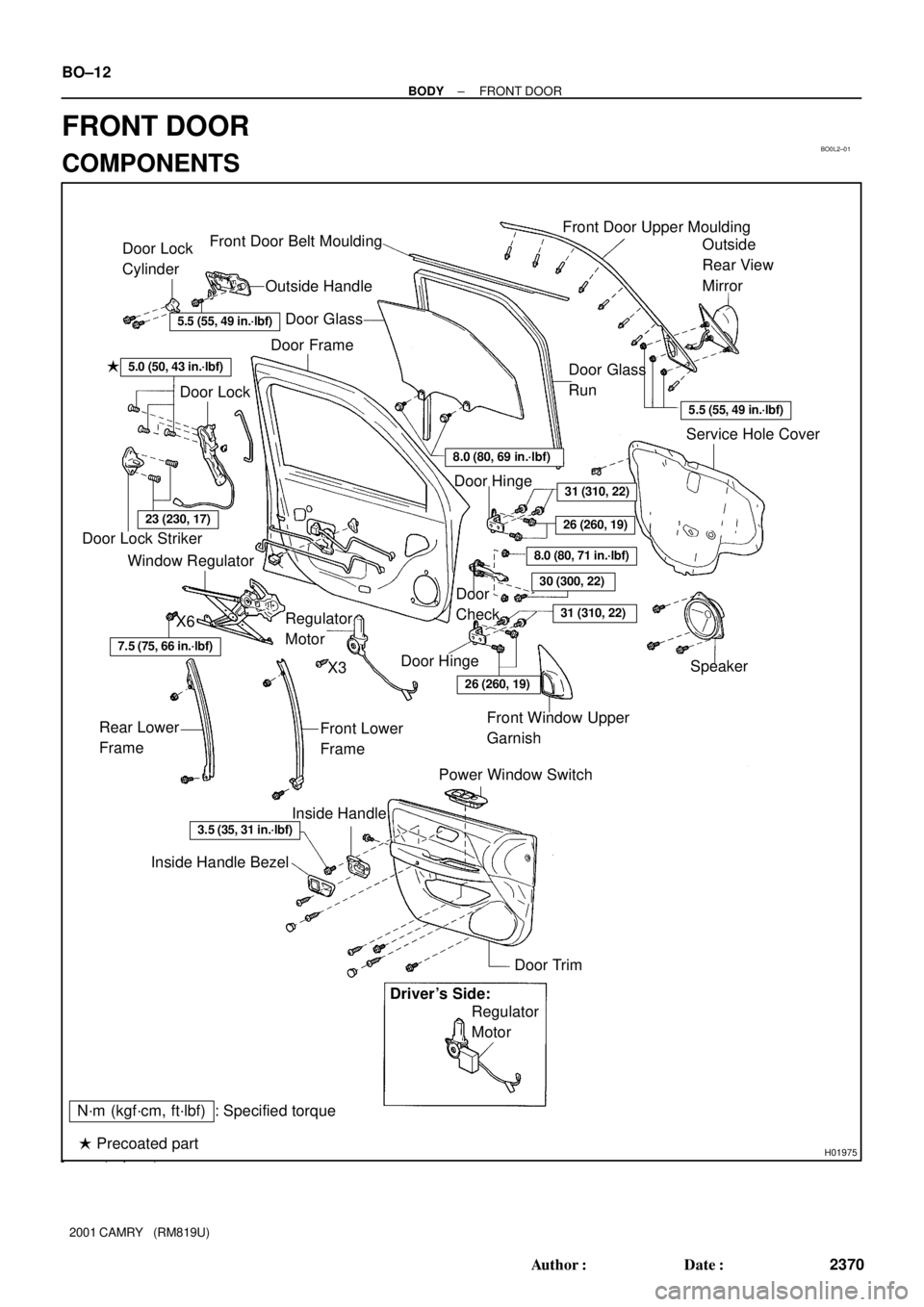
BO0L2±01
H01975
Door Lock
Cylinder
Outside Handle Front Door Belt Moulding
Door Glass
Door FrameFront Door Upper Moulding
Outside
Rear View
Mirror
Door Glass
Run
5.5 (55, 49 in.´lbf)
5.5 (55, 49 in.´lbf)
5.0 (50, 43 in.´lbf)�
Door Lock
23 (230, 17)
Window Regulator
8.0 (80, 69 in.´lbf)
Door Hinge
X6
7.5 (75, 66 in.´lbf)
Regulator
Motor
X3
31 (310, 22)
26 (260, 19)
8.0 (80, 71 in.´lbf)
30 (300, 22)
31 (310, 22)
Door
Check
Door Hinge
26 (260, 19)
Speaker
Power Window Switch Rear Lower
FrameFront Lower
FrameFront Window Upper
Garnish
Inside Handle Bezel
3.5 (35, 31 in.´lbf)
Driver's Side:
Regulator
Motor
Ptdt
N´m (kgf´cm, ft´lbf) : Specified torqueInside Handle
Door Trim
� Precoated part Door Lock StrikerService Hole Cover BO±12
± BODYFRONT DOOR
2370 Author�: Date�:
2001 CAMRY (RM819U)
FRONT DOOR
COMPONENTS
Page 3624 of 4770
N20970
(a)
(b)(b)
N21004
Clip
H01729
: 7 rivets
: clip
: clip
: clip BO±14
± BODYFRONT DOOR
2372 Author�: Date�:
2001 CAMRY (RM819U)
8. REMOVE DOOR GLASS
(a) Open the door glass until the bolt appears in the service
hole.
(b) Remove the 2 bolts and the door glass.
HINT:
Pull the glass upward.
Torque: 8.0 N´m (80 kgf´cm, 71 in.´lbf)
9. REMOVE GLASS RUN
HINT:
Pull the glass run upward.
10. REMOVE FRONT AND REAR SIDE FRAMES
Remove the 2 bolts, 2 nuts and the side frames.
HINT:
Remove the side frames through the service hole.
11. REMOVE FRONT DOOR BELT MOULDING
Pry the rearward end of the front door belt moulding from the
door and remove the moulding.
12. REMOVE FRONT DOOR UPPER MOULDING
(a) Using a drill, cut the flange portion of the 7 rivets.
HINT:
At the time of assembly, please refer to the following item.
Use 7 new rivets.
(b) Pry out the 2 clips and remove the moulding.
Page 3627 of 4770
BO0L6±01
H01733
Door LockRear Door Upper
Moulding
Door Belt Moulding
Door Glass
Outside handle
Door Glass Run
Door Lock
Door Lock Striker
Rear Side Frame
Rear Door WeatherstripWindow Regulator
Inside Handle BezelInside HandleWindow
Regulator
Motor Child Protector
Lock Lever Cover
Snap Ring
Regulator
Handle Plate Door Trim Service Hole Cover Power Window
Switch Cover Door HingeDoor Hinge
Door Check w/o Power Door
Lock:
w/o Power Window:
: Specified torque
N´m (kgf´cm, ft´lbf)
3.5 (35, 31 in.´lbf)
5.5 (55, 49 in.´lbf)
5.5 (55, 49 in.´lbf)
23 (230, 17)
7.0 (70, 61 in.´lbf)
Door Lock Control Link
Door Lock Remote
Control Link
5.0 (50, 43 in.´lbf)
8.0 (80, 71 in.´lbf)
26 (260, 19)
8.0 (80, 71 in.´lbf)
30 (300, 22)
26 (260, 19)
BO±18
± BODYREAR DOOR
2376 Author�: Date�:
2001 CAMRY (RM819U)
REAR DOOR
COMPONENTS
Page 3629 of 4770
N20974
(b)(b)
(a)
N21008
Clip
H01743
: 7 rivets
: clips
: clips
: clips BO±20
± BODYREAR DOOR
2378 Author�: Date�:
2001 CAMRY (RM819U)
7. REMOVE DOOR GLASS AND RUN
(a) Remove the bolt and nut holding the rear side frame to the
door.
(b) Remove the 2 bolts holding the door glass to the window
regulator.
Torque: 8.0 N´m (80 kgf´cm, 71 in.´lbf)
(c) Remove the rear side frame and the rear section of the
door glass run.
Torque: 5.5 N´m (55 kgf´cm, 49 in.´lbf)
HINT:
Pull the door glass run upward.
(d) Remove the door glass.
(e) Remove the entire door glass run.
HINT:
Pull the door glass run upward.
8. REMOVE REAR DOOR BELT MOULDING
Pry the rearward end of the rear door belt moulding from the
door and remove the moulding.
9. REMOVE REAR DOOR UPPER MOULDING
(a) Using a drill, cut the flange portion of the 5 rivets.
HINT:
Use 5 new rivets.
(b) Insert a screwdriver between the door and the rear door
upper moulding and pry it off.
Page 4031 of 4770

SS0BY±01
± SERVICE SPECIFICATIONSBODY
SS±69
232 Author�: Date�:
BODY
TORQUE SPECIFICATION
Part tightenedN´mkgf´cmft´lbf
FRONT BUMPER±±±
Front bumper cover x Body5.55549 in.´lbf
Front bumper reinforcement x Body3435025
REAR BUMPER±±±
Rear bumper cover x Body5.05043 in.´lbf
Rear bumper reinforcement x Body3435025
HOOD±±±
Hood hinge x Hood2626019
Hood lock x Body8.08071 in.´lbf
FRONT AND REAR DOOR±±±
Front door hinge x Body3131022
Rear door hinge x Body2626019
Door hinge x Door panel2626019
Door lock striker x Body2626019
Outside rear view mirror x Front door panel5.55549
Door inside handle x Door panel3.53531 in.´lbf
Door glass x Window regulator8.08071 in.´lbf
Window regulator x Door panel5.55549 in.´lbf
Door lock x Door panel5.05043 in.´lbf
Door outside handle x Door panel7.07061 in.´lbf
Door check x Body3030022
Door check x Door panel8.08071 in.´lbf
LUGGAGE COMPARTMENT DOOR AND HINGE±±±
Luggage door hinge x Luggage door8.08071 in.´lbf
Luggage door lock striker x Body5.55549 in.´lbf
Luggage door lock x Luggage door5.55549 in.´lbf
FRONT WIPER AND WASHER±±±
Wiper motor assembly x Body2424518
Wiper arm x Wiper pivot5.55549 in.´lbf
SLIDING ROOF±±±
Sliding roof assembly x Body5.55549 in.´lbf
INSTRUMENT PANEL±±±
Front passenger airbag assembly x Reinforcement2020014
Steering wheel lock nut3536026
SEAT±±±
Front Seat (Power Seat for TMC Made)±±±
Hinge cover x Seatback frame1818513
Seatback frame x Power seat adjuster1515011
Seatback frame x Side airbag assembly6.06153 in.´lbf
Front Seat (Manual Seat for TMC Made)±±±
Front seat adjuster x Body3737527
Page 4470 of 4770
DOOR GLASS DISPLACEMENT FIELD FIX ± BO012±99 September 3, 1999
Page 2 of 2
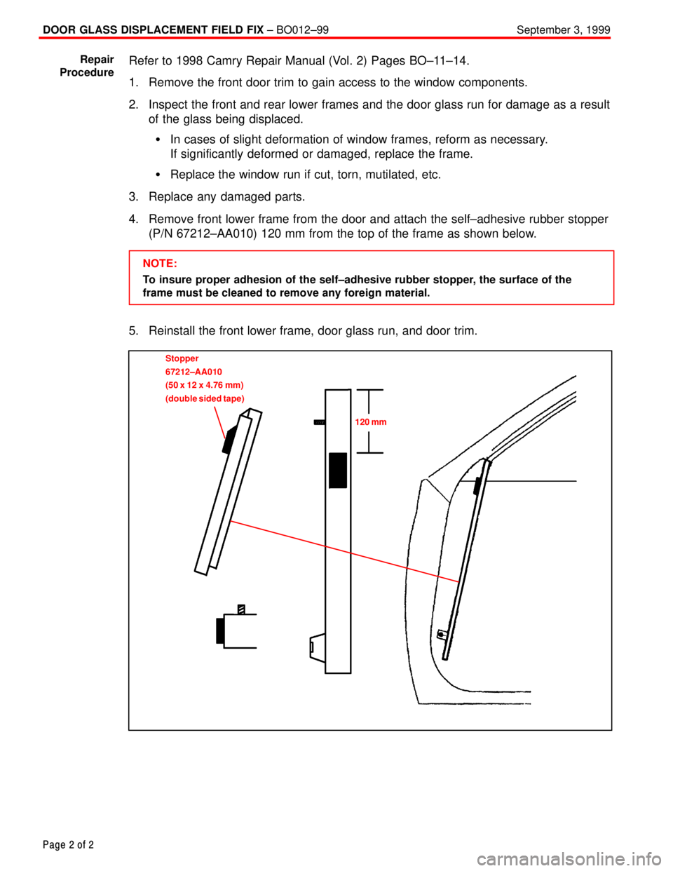
Refer to 1998 Camry Repair Manual (Vol. 2) Pages BO±11±14.
1. Remove the front door trim to gain access to the window components.
2. Inspect the front and rear lower frames and the door glass run for damage as a result
of the glass being displaced.
In cases of slight deformation of window frames, reform as necessary.
If significantly deformed or damaged, replace the frame.
Replace the window run if cut, torn, mutilated, etc.
3. Replace any damaged parts.
4. Remove front lower frame from the door and attach the self±adhesive rubber stopper
(P/N 67212±AA010) 120 mm from the top of the frame as shown below.
NOTE:
To insure proper adhesion of the self±adhesive rubber stopper, the surface of the
frame must be cleaned to remove any foreign material.
5. Reinstall the front lower frame, door glass run, and door trim.
Stopper
67212±AA010
(50 x 12 x 4.76 mm)
(double sided tape)
120 mm
Repair
Procedure
Page 4477 of 4770
DOOR GLASS DISPLACEMENT ± BO017±99 November 26, 1999
Page 2 of 2
1. Lower the door glass, disconnect the power window switch, remove the front door
trim panel, speaker, and loosen the door mirror mounts to gain access to the door
glass and lower frames. Remove the front lower frame (2 screws).
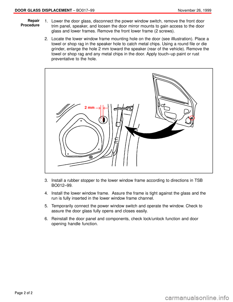
2. Locate the lower window frame mounting hole on the door (see illlustration). Place a
towel or shop rag in the speaker hole to catch metal chips. Using a round file or die
grinder, enlarge the hole 2 mm toward the speaker (rear of the vehicle). Remove the
towel or shop rag and any metal chips in the door. Apply touch±up paint or rust
preventative to the hole.
2 mm"u
3. Install a rubber stopper to the lower window frame according to directions in TSB
BO012±99.
4. Install the lower window frame. Assure the frame is tight against the glass and the
run is fully inserted in the lower window frame channel.
5. Temporarily connect the power window switch and operate the window. Check to
assure the door glass fully opens and closes easily.
6. Reinstall the door panel and components, check lock/unlock function and door
opening handle function.
Repair
Procedure