Page 1509 of 4770
K POWER SOURCE (Current Flow Chart)
Engine Room R/B No.2 (See Page 24)
FuseSystemPage
5ADRL NO.2Headlight (w/ Daytime Running Light)100
10AH±LP LH (LWR)Headlight (w/ Daytime Running Light)100
10AH±LP RH (LWR)Headlight (w/ Daytime Running Light)100
Engine Room R/B No.3 (TMMK Made w/ ABS and Traction Control)
(TMC Made w/ ABS, w/ ABS and Traction Control)
or
Fusible Link Block
(TMMK Made w/ ABS w/o Traction Control) (See Page 25)
FuseSystemPage
60AFL ABS
ABS (TMC Made)
ABS (TMMK Made)
ABS and Traction Control234
240
226
*These are the page numbers of the first page on which the related system is shown.
Page 2426 of 4770
DI±6
± DIAGNOSTICSENGINE (5S±FE)
241 Author�: Date�:
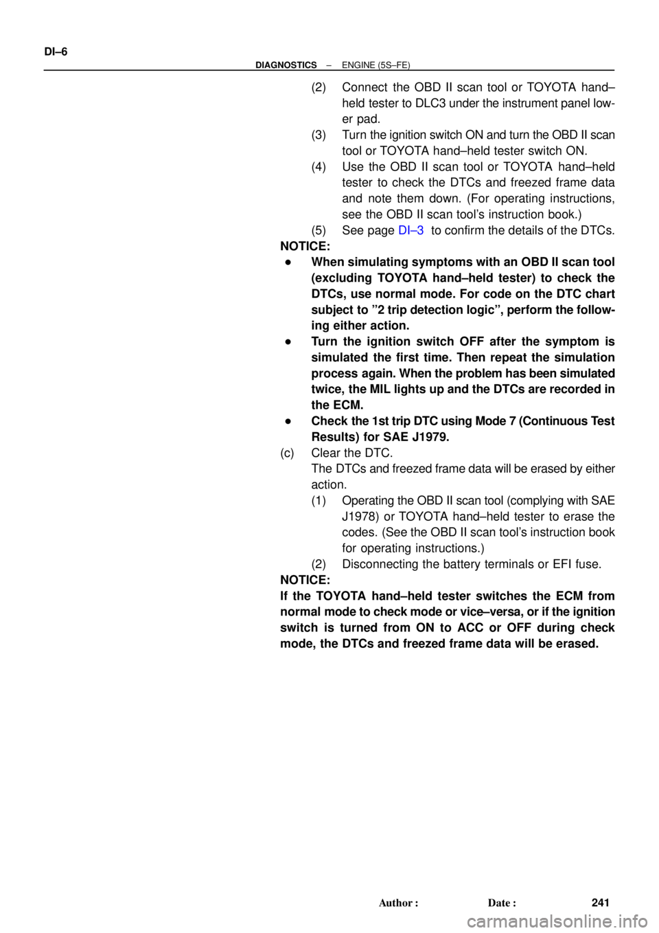
(2) Connect the OBD II scan tool or TOYOTA hand±
held tester to DLC3 under the instrument panel low-
er pad.
(3) Turn the ignition switch ON and turn the OBD II scan
tool or TOYOTA hand±held tester switch ON.
(4) Use the OBD II scan tool or TOYOTA hand±held
tester to check the DTCs and freezed frame data
and note them down. (For operating instructions,
see the OBD II scan tool's instruction book.)
(5) See page DI±3 to confirm the details of the DTCs.
NOTICE:
�When simulating symptoms with an OBD II scan tool
(excluding TOYOTA hand±held tester) to check the
DTCs, use normal mode. For code on the DTC chart
subject to º2 trip detection logicº, perform the follow-
ing either action.
�Turn the ignition switch OFF after the symptom is
simulated the first time. Then repeat the simulation
process again. When the problem has been simulated
twice, the MIL lights up and the DTCs are recorded in
the ECM.
�Check the 1st trip DTC using Mode 7 (Continuous Test
Results) for SAE J1979.
(c) Clear the DTC.
The DTCs and freezed frame data will be erased by either
action.
(1) Operating the OBD II scan tool (complying with SAE
J1978) or TOYOTA hand±held tester to erase the
codes. (See the OBD II scan tool's instruction book
for operating instructions.)
(2) Disconnecting the battery terminals or EFI fuse.
NOTICE:
If the TOYOTA hand±held tester switches the ECM from
normal mode to check mode or vice±versa, or if the ignition
switch is turned from ON to ACC or OFF during check
mode, the DTCs and freezed frame data will be erased.
Page 2620 of 4770
DI±200
± DIAGNOSTICSENGINE (1MZ±FE)
435 Author�: Date�:
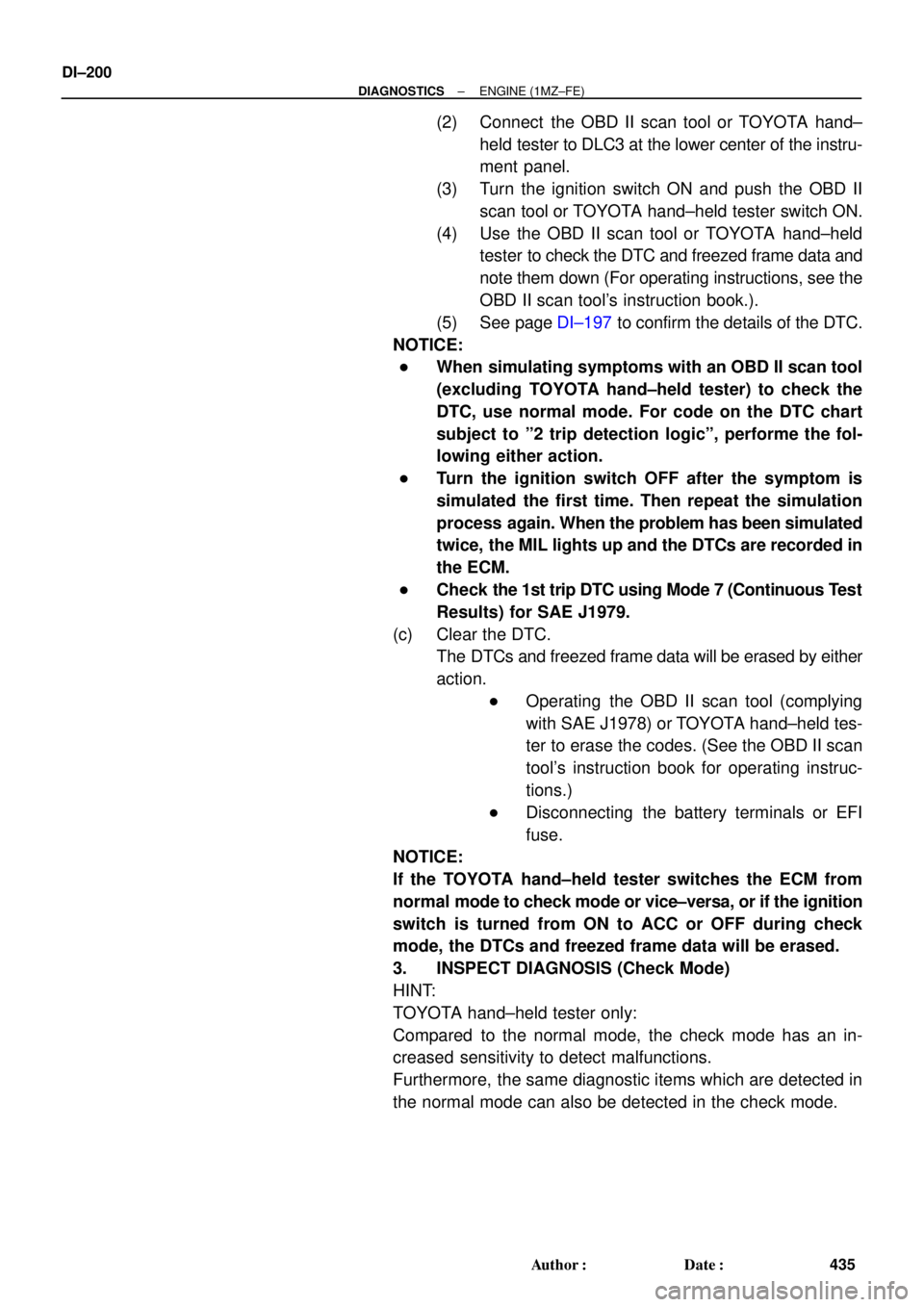
(2) Connect the OBD II scan tool or TOYOTA hand±
held tester to DLC3 at the lower center of the instru-
ment panel.
(3) Turn the ignition switch ON and push the OBD II
scan tool or TOYOTA hand±held tester switch ON.
(4) Use the OBD II scan tool or TOYOTA hand±held
tester to check the DTC and freezed frame data and
note them down (For operating instructions, see the
OBD II scan tool's instruction book.).
(5) See page DI±197 to confirm the details of the DTC.
NOTICE:
�When simulating symptoms with an OBD II scan tool
(excluding TOYOTA hand±held tester) to check the
DTC, use normal mode. For code on the DTC chart
subject to º2 trip detection logicº, performe the fol-
lowing either action.
�Turn the ignition switch OFF after the symptom is
simulated the first time. Then repeat the simulation
process again. When the problem has been simulated
twice, the MIL lights up and the DTCs are recorded in
the ECM.
�Check the 1st trip DTC using Mode 7 (Continuous Test
Results) for SAE J1979.
(c) Clear the DTC.
The DTCs and freezed frame data will be erased by either
action.
�Operating the OBD II scan tool (complying
with SAE J1978) or TOYOTA hand±held tes-
ter to erase the codes. (See the OBD II scan
tool's instruction book for operating instruc-
tions.)
�Disconnecting the battery terminals or EFI
fuse.
NOTICE:
If the TOYOTA hand±held tester switches the ECM from
normal mode to check mode or vice±versa, or if the ignition
switch is turned from ON to ACC or OFF during check
mode, the DTCs and freezed frame data will be erased.
3. INSPECT DIAGNOSIS (Check Mode)
HINT:
TOYOTA hand±held tester only:
Compared to the normal mode, the check mode has an in-
creased sensitivity to detect malfunctions.
Furthermore, the same diagnostic items which are detected in
the normal mode can also be detected in the check mode.
Page 2985 of 4770
F00096
J/C
J4 D
ABS 7
C
R±LC10
1D
GAUGE
A6 4
DLC2ECU
Instrument
Panel J/BABS
Warning
Light
210
IG312
C10
DR±L R±L
WA 21
14 R±LJ/C
J29
C
C R±L
R±LR±L
IK3
± DIAGNOSTICSANTI±LOCK BRAKE SYSTEM (BOSCH Made)
DI±565
800 Author�: Date�:
ABS Warning Light Circuit
CIRCUIT DESCRIPTION
If the ECU detects any trouble, it lights the ABS warning light while at the same time prohibiting ABS control.
At this time, the ECU records a DTC in memory.
Connect terminals Tc and E
1 of the DLC1 or DLC2 to make the ABS warning light blink and output the DTC.
WIRING DIAGRAM
INSPECTION PROCEDURE
Troubleshoot in accordance with the chart below for each trouble symptom
ABS warning light does not light upGo to step 1
ABS warning light remains onGo to step 2
1 Check ABS warning light.
See combination meter troubleshooting on page BE±2.
NG Repair bulb or combination meter assembly.
OK
Check for open circuit in harness and connector between GAUGE fuse, DLC2 and ABS ECU
(See page IN±31).
DI048±08
Page 3295 of 4770
DI08I±08
± DIAGNOSTICSCRUISE CONTROL SYSTEM
DI±875
111 0 Author�: Date�:
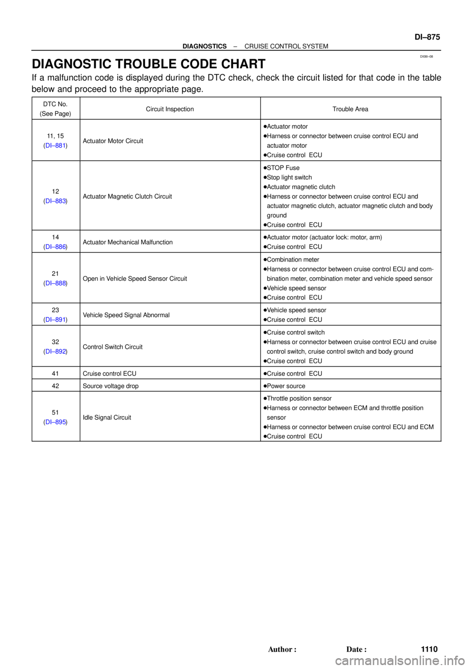
DIAGNOSTIC TROUBLE CODE CHART
If a malfunction code is displayed during the DTC check, check the circuit listed for that code in the table
below and proceed to the appropriate page.
DTC No.
(See Page)Circuit InspectionTrouble Area
11, 15
(DI±881)Actuator Motor Circuit
�Actuator motor
�Harness or connector between cruise control ECU and
actuator motor
�Cruise control ECU
12
(DI±883)Actuator Magnetic Clutch Circuit
�STOP Fuse
�Stop light switch
�Actuator magnetic clutch
�Harness or connector between cruise control ECU and
actuator magnetic clutch, actuator magnetic clutch and body
ground
�Cruise control ECU
14
(DI±886)Actuator Mechanical Malfunction�Actuator motor (actuator lock: motor, arm)
�Cruise control ECU
21
(DI±888)Open in Vehicle Speed Sensor Circuit
�Combination meter
�Harness or connector between cruise control ECU and com-
bination meter, combination meter and vehicle speed sensor
�Vehicle speed sensor
�Cruise control ECU
23
(DI±891)Vehicle Speed Signal Abnormal�Vehicle speed sensor
�Cruise control ECU
32
(DI±892)Control Switch Circuit
�Cruise control switch
�Harness or connector between cruise control ECU and cruise
control switch, cruise control switch and body ground
�Cruise control ECU
41Cruise control ECU�Cruise control ECU
42Source voltage drop�Power source
51
(DI±895)Idle Signal Circuit
�Throttle position sensor
�Harness or connector between ECM and throttle position
sensor
�Harness or connector between cruise control ECU and ECM
�Cruise control ECU

