Page 3419 of 4770

Length = 230 mm (9.06 in.)
± ENGINE MECHANICAL (5S±FE)TIMING BELT
EM±27
1199 Author�: Date�:
(b) Slowly turn the crankshaft")
S05587
Turn
S05598
S05586
Turn
S05585
S01710
Length = 735 mm (28.94 in.)
Length = 230 mm (9.06 in.)
± ENGINE MECHANICAL (5S±FE)TIMING BELT
EM±27
1199 Author�: Date�:
(b) Slowly turn the crankshaft pulley 2 revolutions TDC to
TDC.
NOTICE:
Always turn the crankshaft pulley clockwise.
(c) Check that each pulley aligns with the timing marks as
shown in the illustration.
If the timing marks do not align, remove the timing belt and rein-
stall it.
(d) Slowly turn the crankshaft pulley 1 and 7/8 revolutions,
and align its groove with the mark at 45° BTDC (for No.1
cylinder) of the No.1 timing belt cover.
NOTICE:
Always turn the crankshaft pulley clockwise.
(e) Tighten the mounting bolt of the No.1 idler pulley.
Torque: 42 N´m (425 kgf´cm, 31 ft´lbf)
13. INSTALL NO.2 TIMING BELT COVER
(a) Check that the timing belt cover gaskets have no cracks
or peeling, etc.
If the gasket has cracks or peeling, etc., replace it using these
steps:
(1) Using a screwdriver and gasket scraper, remove all
the old gasket material.
(2) Thoroughly clean all components to remove all the
loose material.
Page 3432 of 4770
CYLINDER HEAD
1212 Author�: Date�:
25. DISASSEMBLE EXHAUST CAMSHAFT
(a) Mount the camshaft")
P05613
S01665
SST
Service
Bolt
S01666
EM7558
6 10
192 8 3
74 5
S05971
Pry EM±40
± ENGINE MECHANICAL (5S±FE)CYLINDER HEAD
1212 Author�: Date�:
25. DISASSEMBLE EXHAUST CAMSHAFT
(a) Mount the camshaft in a vise.
NOTICE:
Be careful not to damage the camshaft.
(b) Using SST, turn the sub±gear clockwise, and remove the
service bolt.
SST 09960±10010 (09962±01000, 09963±00500)
(c) Using snap ring pliers, remove the snap ring.
(d) Remove the wave washer, camshaft sub±gear and gear
spring.
26. REMOVE CYLINDER HEAD
(a) Disconnect the camshaft position sensor connector.
(b) Remove the 2 bolts holding the water bypass pipe to the
cylinder head.
(c) Uniformly loosen and remove the 10 cylinder head bolts
in several passes, in the sequence shown.
NOTICE:
Cylinder head warpage or cracking could result from re-
moving bolts in incorrect order.
(d) Lift the cylinder head from the dowels on the cylinder
block, and place the cylinder head on wooden blocks on
a bench.
HINT:
If the cylinder head is off, pry between the cylinder head and cyl-
inder block with a screwdriver.
NOTICE:
Be careful not to damage the contact surfaces of the cylin-
der head and cylinder block.
Page 3446 of 4770
CYLINDER HEAD
1226 Author�: Date�:
4. ASSEMBLE EXHAUST CAMSHA")
P05617
Z02838
Wave Washer
Sub±Gear
Gear Spring
S01666
S01664
SST
Turn Sub±Gear
Service
BoltMain Gear EM±54
± ENGINE MECHANICAL (5S±FE)CYLINDER HEAD
1226 Author�: Date�:
4. ASSEMBLE EXHAUST CAMSHAFT
(a) Mount the camshaft in a vise.
NOTICE:
Be careful not to damage the camshaft.
(b) Install the camshaft gear spring, camshaft sub±gear and
wave washer.
HINT:
Align the pins on the gears with the spring ends.
(c) Using snap ring pliers, install the snap ring.
(d) Using SST, align the holes of the camshaft drive gear and
sub±gear by turning camshaft sub±gear clockwise, and
install a service bolt.
SST 09960±10010 (09962±01000, 09963±00500)
(e) Align the gear teeth of the drive gear and sub±gear, and
tighten the service bolt.
5. INSTALL CAMSHAFTS
NOTICE:
Since the thrust clearance of the camshaft is small, the
camshaft must be kept level while it is being installed. If the
camshaft is not kept level, the portion of the cylinder head
receiving the shaft thrust may crack or be damaged, caus-
ing the camshaft to seize or break. To avoid this, the follow-
ing steps should be carried out.
Page 3448 of 4770
CYLINDER HEAD
1228 Author�: Date�:
(b) Install the exhaust c")
P03281
10 ± 45°
Knock
Pin
P03373
Assembly
Reference Mark
Timing
Mark
P03374
P03375
1 2
3 410
5 6
8
79 EM±56
± ENGINE MECHANICAL (5S±FE)CYLINDER HEAD
1228 Author�: Date�:
(b) Install the exhaust camshaft.
(1) Set the knock pin of the intake camshaft at 10 ± 45°
BTDC of camshaft angle.
HINT:
The above angle allows the No.2 and No.4 cylinder cam lobes
of the exhaust camshaft to push their valve lifters evenly.
(2) Apply MP grease to the thrust portion of the cam-
shaft.
(3) Engage the exhaust camshaft gear to the intake
camshaft gear by matching the timing marks on
each gear.
(4) Roll down the exhaust camshaft onto the bearing
journals while engaging gears with each other.
NOTICE:
There are also assembly reference marks on each gear as
shown in the illustration. Do not use these marks.
(5) Turn the intake camshaft clockwise or counterclock-
wise a little until the exhaust camshaft sits in the
bearing journals evenly without rocking the cam-
shaft on the bearing journals.
NOTICE:
It is very important to replace the camshaft in the bearing
journals evenly while tightening bearing caps in the subse-
quent steps.
(6) Install the bearing caps in their proper locations.
(7) Apply a light coat of engine oil on the threads and
under the heads of the bearing cap bolts.
(8) Install and uniformly tighten the 10 bearing cap
bolts in several passes, in the sequence shown.
Torque: 19 N´m (190 kgf´cm, 14 ft´lbf)
Page 3451 of 4770
S06009
Upward
ConnectorTurn
Push
S05935New Insulator
Spacer
S06002
S06003
Upward
ConnectorTurn
S06001
± ENGINE MECHANICAL (5S±FE)CYLINDER HEAD
EM±59
1231 Author�: Date�:
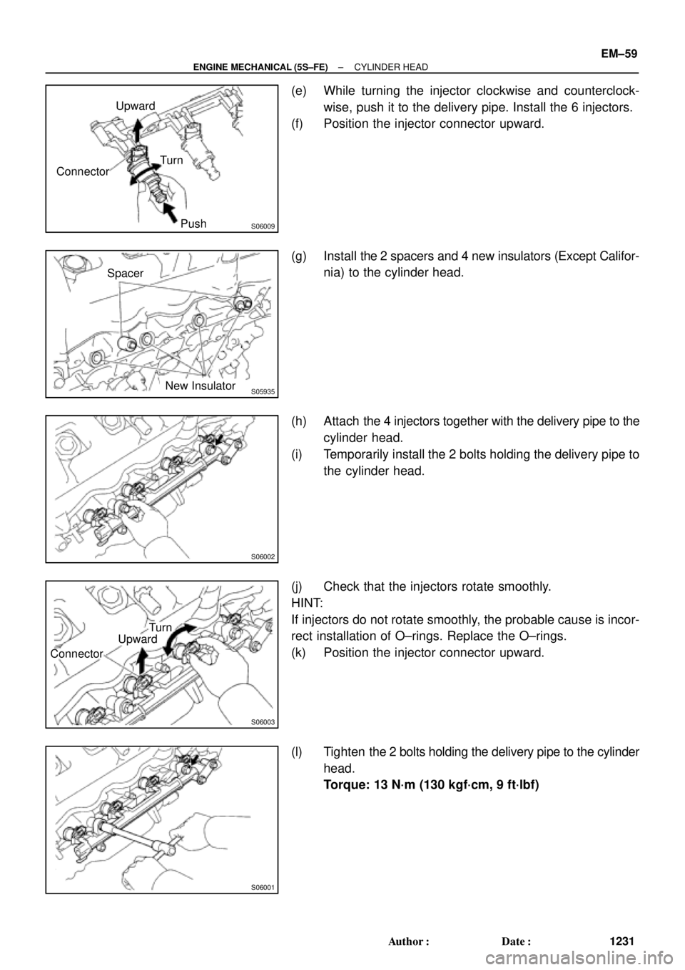
(e) While turning the injector clockwise and counterclock-
wise, push it to the delivery pipe. Install the 6 injectors.
(f) Position the injector connector upward.
(g) Install the 2 spacers and 4 new insulators (Except Califor-
nia) to the cylinder head.
(h) Attach the 4 injectors together with the delivery pipe to the
cylinder head.
(i) Temporarily install the 2 bolts holding the delivery pipe to
the cylinder head.
(j) Check that the injectors rotate smoothly.
HINT:
If injectors do not rotate smoothly, the probable cause is incor-
rect installation of O±rings. Replace the O±rings.
(k) Position the injector connector upward.
(l) Tighten the 2 bolts holding the delivery pipe to the cylinder
head.
Torque: 13 N´m (130 kgf´cm, 9 ft´lbf)
Page 3480 of 4770
CYLIN")
Z19412
No.1 Balance
Shaft Mark A
Mark B No.2 Housing
S05942
Measuring Point
for Dial Indicator
SST
S05943
Z19414
No.1 Balance
Shaft
Mark A Mark B
No.2 Housing EM±88
± ENGINE MECHANICAL (5S±FE)CYLINDER BLOCK
1260 Author�: Date�:
(d) First turn the crankshaft clockwise, and align the groove
of the No.2 balance shaft housing with punch mark A of
the No.1 balance shaft.
(e) Set SST and a dial indicator as shown in the illustration.
SST 09224±74010
HINT:
Make sure that the needle of the dial indicator is perpendicular
to the SST and that it is placed in the middle of the 3rd indention.
(f) Lightly turn the No.1 balance shaft by hand and measure
the backlash.
HINT:
�Turn the No.1 balance shaft 4 or 5 times to provide a
steady backlash reading.
�To prevent excessive backlash due to thrust clearance,
measure the backlash while pressing on the rear of the
No.1 balance shaft.
Standard backlash (at punch mark A):
0.005 ± 0.040 mm (0.0002 ± 0.0016 in.)
NOTICE:
Do not turn the No.1 balance shaft strongly.
(g) Remove the dial indicator and SST.
(h) Turn the crankshaft clockwise to align the groove of the
No.2 housing with punch mark B.
(i) Set the dial indicator. (See step (e))
(j) Measure the backlash. (See step (f))
Standard backlash (at punch mark B):
0.005 ± 0.060 mm (0.0002 ± 0.0024 in.)
(k) Remove the dial indicator.
Page 3481 of 4770
CYLINDER BLOCK
EM±89
1261 Author�: Date�:
(l) Turn the crankshaf")
Z19412
No.1 Balance
Shaft Mark A
Mark B No.2 Housing
Z19414
Mark B
No.2 Housing
Mark A No.1 Balance
Shaft
± ENGINE MECHANICAL (5S±FE)CYLINDER BLOCK
EM±89
1261 Author�: Date�:
(l) Turn the crankshaft clockwise again to align the groove
of the No.2 housing with punch mark A.
(m) Set the dial indicator. (See step (e))
(n) Measure the backlash. (See step (f))
Standard backlash (at punch mark A):
0.005 ± 0.040 mm (0.0002 ± 0.0016 in.)
(o) Remove the dial indicator.
(p) Turn the crankshaft clockwise again to align the groove
of the No.2 housing with punch mark B.
(q) Set the dial indicator. (See step (e))
(r) Measure the backlash. (See step (f))
Standard backlash (at punch mark B):
0.005 ± 0.060 mm (0.0002 ± 0.0024 in.)
(s) Remove the dial indicator.
If even one of the 4 points measured above exceeds the back-
lash specification, adjust the backlash with new spacers.
NOTICE:
Use the same size spacers for both the left and right sides.
HINT:
�Varying the spacer thickness by 0.02 mm (0.0008 in.)
change the backlash by about 0.014 mm (0.0006 in.).
�If the backlash is greater than permitted maximum, select
a thinner shim.
�If the backlash is less than the specification, select a thick-
er shim.
Page 3506 of 4770
EM08M±03
A07369
Heated Oxygen Sensor (Bank 1 Sensor 2)
HINT:
Before installing oxygen sensor, twist
sensor wire counterclockwise 3 and 1/2
turns.
After installing oxygen sensor, check that
sensor wire is not twisted. If it is twisted,
remove oxygen sensor and reinstall it.
Heat Insulator
Bracket
RingTailpipe
� Gasket
Center Exhaust Pipe
Heated Oxygen Sensor
(Bank 1 Sensor 2)
TWC (Except California)
Rear TWC (California)
Front Exhaust Pipe Bracket
StayBracket
N´m (kgf´cm, ft´lbf)
� Non±reusable part� Gasket
� Gasket
�Heat Insulator Heat Insulator
Heat Insulator
�
56 (570, 41)
44 (450, 32)
62 (630, 46)
56 (570, 41)
�Bracket
: Specified torqueRing �
�
19 (195, 14)
33 (330, 24)
33 (330, 24)
33 (330, 24)
EM±114
± ENGINE MECHANICAL (5S±FE)EXHAUST SYSTEM
1286 Author�: Date�:
EXHAUST SYSTEM
COMPONENTS

HINT:
Before installing oxygen sensor, twist
sensor wire counterclockwise 3 and 1/2
turns.
After installing oxygen sensor, check that
sensor wir")