Page 1869 of 4770
AUTOMATIC TRANSAXLEOVERDRIVE UNIT ±
AX±73
(e) Install the snap ring.
12. CHECK OPERATION OF O/D ONE±WAY CLUTCH
(a) Install the overdrive direct clutch into the one±way clutch.
(b) Hold the overdrive direct clutch and turn the intermediate
shaft. The shaft should turn freely clockwise and should
lock counterclockwise.
(c) Remove the overdrive direct clutch.
OVERDRIVE CASE DISASSEMBLY
1. REMOVE C0 ACCUMULATOR PISTON FROM OVER-
DRIVE CASE
(a) Using snap ring pliers, remove the snap ring.
(b) Remove the retaining plate and 2 springs.
(c) Remove the accumulator piston.
(d) Remove the O±ring from the piston.
AX041±02
Page 1872 of 4770
AUTOMATIC TRANSAXLEOVERDRIVE UNIT ±
AX±76
4. INSTALL SNAP RING INTO CASE
Be sure the end gap of the snap ring is not aligned with
one of cutouts.
5. INSTALL OVERDRIVE PLANETARY GEAR ONTO OV-
ERDRIVE DIRECT CLUTCH
While turning the overdrive planetary gear clockwise,
install it onto the overdrive direct clutch.
HINT: If the overdrive planetary gear is properly installed
onto the direct clutch, the counter drive gear height from
the overdrive case will be about 24 mm (0.94 in.).
Page 1899 of 4770

AUTOMATIC TRANSAXLECOMPONENT PARTS INSTALLATION ±
AX±103
2. PLACE OIL SLINGER AND NEW SPACER
HINT: Install the spacer with the small end downward.
3. INSTALL OUTER RACE TO TRANSAXLE CASE
Using SST, press in the outer race.
SST 09350±32014 (09351±32100, 09351±32140)
4. INSTALL COUNTER DRIVE GEAR
(a) Place a brass bar into the transaxle hole to hold the drive
pinion shaft.
(b) Using SST, press in the counter driven gear until the
counter driven gaer bearing almost touches the counter
gear.
SST 09350±32014 (09351±32140)
5. INSTALL NEW LOCK NUT AND ADJUST DRIVE PIN-
ION PRELOAD
(a) Install the new lock nut.
(b) Using SST to hold the gear, tighten the nut.
Torque: 280 N´m (2,855 kgf´cm, 206 ft´lbf)
SST 09330±00021, 09350±32014 (09351±32032)
(c) Turn the gear counterclockwise and clockwise several
times.
(d) Using a small torque wrench, measure the preload of the
drive pinion.
Drive pinion preload (at starting):
New bearing
1.0±1.6 N´m (10±16 kgf´cm, 8.7±13.9 in.´lbf)
Reused bearing
0.5±0.8 N´m (5±8 kgf´cm, 4.3±6.9 in.´lbf)
�If the preload is greater than specified, replace the
bearing spacer.
Page 1910 of 4770
AUTOMATIC TRANSAXLECOMPONENT PARTS INSTALLATION ±
AX±114
13. INSTALL NO.2 ONE±WAY CLUTCH INTO CASE
(a) Place the No.2 one±way clutch with the shiny side of
flange upward.
(b) Install the one±way clutch while turning the planetary
gear clockwise with SST.
SST 09350±32014 (09351±32050)
If the planetary gear cannot turn clockwise, check the
installation of the one±way clutch.
(c) Install the snap ring.
HINT: Be sure that the end gap of the snap ring is not
aligned with one of cutouts.
(d) Coat the thrust washer with petroleum jelly and install it
onto the rear planetary gear.
14. INSTALL SECOND COAST BRAKE BAND GUIDE
15. PLACE NO.1 ONE±WAY CLUTCH
(a) Coat the thrust washer with petroleum jelly and install it
on the No.1 one±way clutch.
Page 1912 of 4770
AUTOMATIC TRANSAXLECOMPONENT PARTS INSTALLATION ±
AX±116
17. INSTALL NEW SECOND BRAKE GASKET
Install a new gasket until it makes contact with the second
brake drum.
18. CHECK OPERATION OF SECOND BRAKE
Apply compressed air into the second brake gasket and
confirm that the piston moves.
19. INSTALL SUN GEAR AND SUN GEAR INPUT DRUM
(a) Coat the thrust washer with petroleum jelly and install it
on the sun gear input drum.
(b) While turning the sun gear clockwise, install it into the
No.1 one±way clutch.
20. INSTALL OIL SEAL RING TO INTERMEDIATE SHAFT
HINT: After installing the oil seal ring, check that it moves
smoothly.
Page 1958 of 4770
TORQUE CONVERTER CLUTCH AND DRIVE PLATE
1950 Author�: Date�:
TORQUE CONVERTER CLUTCH
AND DRIVE PL")
AX040±01
AT0952
SST
AT0953
SST
AT3306
Hold
Lock
Free
Turn
AT2821
AX±30
± AUTOMATIC TRANSAXLE (A541E)TORQUE CONVERTER CLUTCH AND DRIVE PLATE
1950 Author�: Date�:
TORQUE CONVERTER CLUTCH
AND DRIVE PLATE
INSPECTION
1. INSPECT ONE±WAY CLUTCH
(a) Install SST into the inner race of the one±way clutch.
SST 09350±32014 (09351±32020)
(b) Install SST so that it fits in the notch of the converter hub
and outer race of the one±way clutch.
SST 09350±32014 (09351±32010)
(c) With the torque converter clutch standing on its side,the
clutch locks when turned counterclockwise, and rotates
freely and smoothly clockwise.
If necessary, clean the converter and retest the clutch.
Replace the converter if the clutch still fails the test.
2. MEASURE DRIVE PLATE RUNOUT AND INSPECT
RING GEAR
(a) Set up a dial indicator, and measure the drive plate run-
out.
(b) Check the damage of the ring gear.
Maximum runout: 0.20 mm (0.0079 in.)
If the runout is not within specification or ring gear is damaged,
replace the drive plate.
Torque: 83 N´m (850 kgf´cm, 61 ft´lbf)
Page 2038 of 4770
BO0MD±01
N21124
± BODYINSTRUMENT PANEL
BO±79
2427 Author�: Date�:
DISASSEMBLY
1. REMOVE THESE PARTS:
(a) No.1 defroster nozzle garnish
(b) No.1 defroster nozzle
(c) RH side defroster duct nozzle
(d) No.1 side defroster duct nozzle
(e) No.1 heater duct to register
(f) No.2 heater duct to register
(g) No.2 register assembly
(h) No.3 register assembly
(i) No.1 register assembly
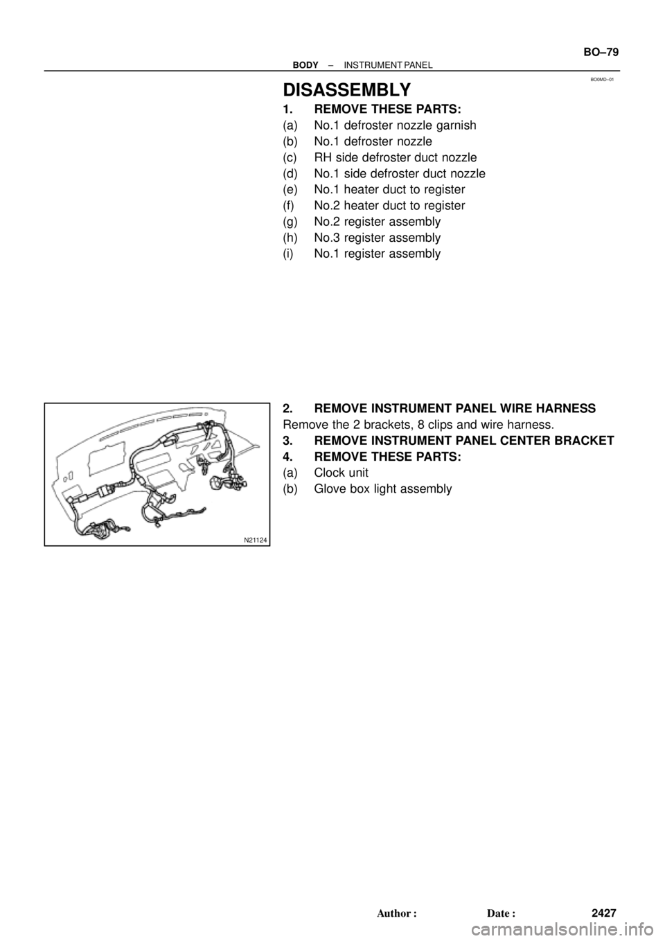
2. REMOVE INSTRUMENT PANEL WIRE HARNESS
Remove the 2 brackets, 8 clips and wire harness.
3. REMOVE INSTRUMENT PANEL CENTER BRACKET
4. REMOVE THESE PARTS:
(a) Clock unit
(b) Glove box light assembly
Page 2158 of 4770
N20555
TMMK made:
TMC made:1
2
N20556
TMMK made:
TMC made:1
2 BE±64
± BODY ELECTRICALPOWER WINDOW CONTROL SYSTEM
2284 Author�: MH Date�: 3/7/02
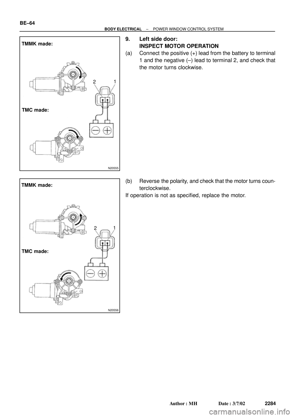
9. Left side door:
INSPECT MOTOR OPERATION
(a) Connect the positive (+) lead from the battery to terminal
1 and the negative (±) lead to terminal 2, and check that
the motor turns clockwise.
(b) Reverse the polarity, and check that the motor turns coun-
terclockwise.
If operation is not as specified, replace the motor.
 Install the snap ring.
12. CHECK OPERATION OF O/D ONE±WAY CLUTCH
(a) Install the overdrive direct clutch into the one±way clutch.
(b) Hold the overdri")

 Place the No.2 one±way clutch with the shiny side of
flange upward.
(b) Install the one±way")