Page 2307 of 4770
CH030±01
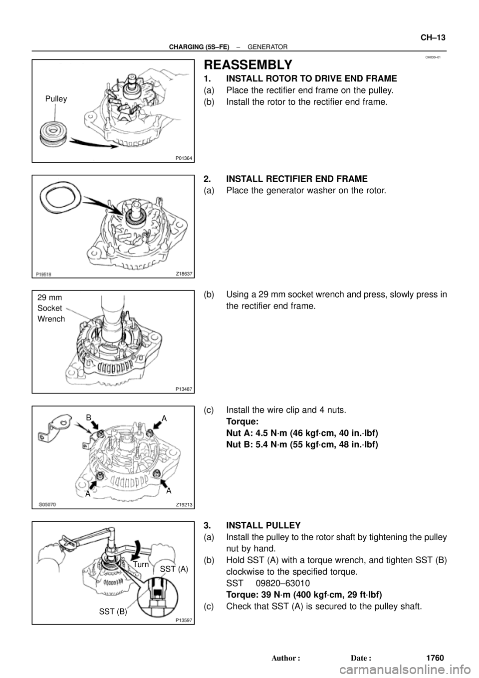
P01364
Pulley
Z18637
P13487
29 mm
Socket
Wrench
Z19213
A B
AA
P13597
SST (A) Turn
SST (B)
± CHARGING (5S±FE)GENERATOR
CH±13
1760 Author�: Date�:
REASSEMBLY
1. INSTALL ROTOR TO DRIVE END FRAME
(a) Place the rectifier end frame on the pulley.
(b) Install the rotor to the rectifier end frame.
2. INSTALL RECTIFIER END FRAME
(a) Place the generator washer on the rotor.
(b) Using a 29 mm socket wrench and press, slowly press in
the rectifier end frame.
(c) Install the wire clip and 4 nuts.
Torque:
Nut A: 4.5 N´m (46 kgf´cm, 40 in.´lbf)
Nut B: 5.4 N´m (55 kgf´cm, 48 in.´lbf)
3. INSTALL PULLEY
(a) Install the pulley to the rotor shaft by tightening the pulley
nut by hand.
(b) Hold SST (A) with a torque wrench, and tighten SST (B)
clockwise to the specified torque.
SST 09820±63010
Torque: 39 N´m (400 kgf´cm, 29 ft´lbf)
(c) Check that SST (A) is secured to the pulley shaft.
Page 2317 of 4770
CH01G±01
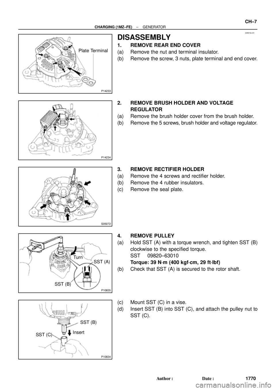
P14233
Plate Terminal
P14234
S05072
P10835
SST (B)SST (A) Turn
P10834
SST (C)SST (B)
Insert
± CHARGING (1MZ±FE)GENERATOR
CH±7
1770 Author�: Date�:
DISASSEMBLY
1. REMOVE REAR END COVER
(a) Remove the nut and terminal insulator.
(b) Remove the screw, 3 nuts, plate terminal and end cover.
2. REMOVE BRUSH HOLDER AND VOLTAGE
REGULATOR
(a) Remove the brush holder cover from the brush holder.
(b) Remove the 5 screws, brush holder and voltage regulator.
3. REMOVE RECTIFIER HOLDER
(a) Remove the 4 screws and rectifier holder.
(b) Remove the 4 rubber insulators.
(c) Remove the seal plate.
4. REMOVE PULLEY
(a) Hold SST (A) with a torque wrench, and tighten SST (B)
clockwise to the specified torque.
SST 09820±63010
Torque: 39 N´m (400 kgf´cm, 29 ft´lbf)
(b) Check that SST (A) is secured to the rotor shaft.
(c) Mount SST (C) in a vise.
(d) Insert SST (B) into SST (C), and attach the pulley nut to
SST (C).
Page 2323 of 4770
CH01J±01
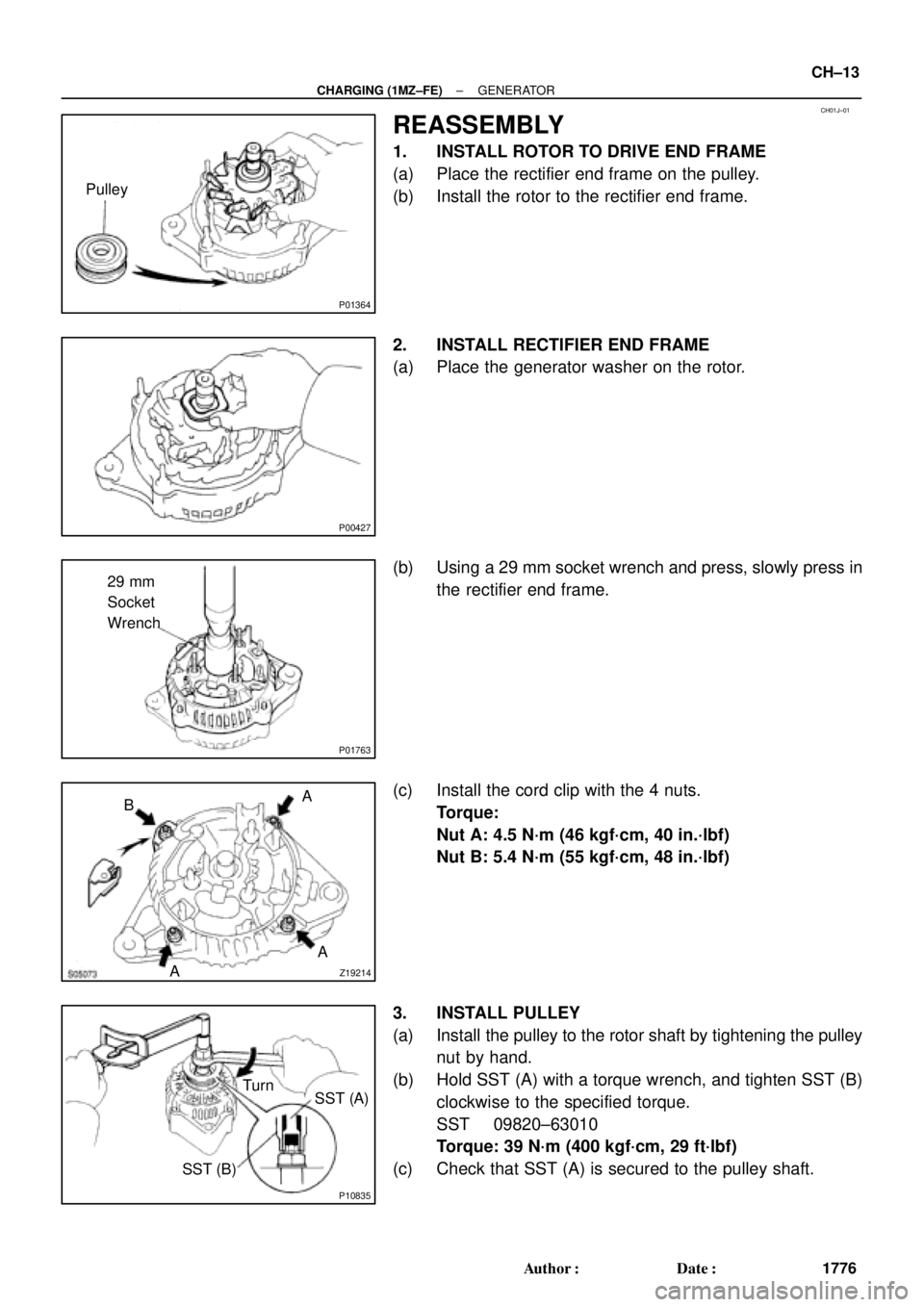
P01364
Pulley
P00427
P01763
29 mm
Socket
Wrench
Z19214AA A
B
P10835
Turn
SST (A)
SST (B)
± CHARGING (1MZ±FE)GENERATOR
CH±13
1776 Author�: Date�:
REASSEMBLY
1. INSTALL ROTOR TO DRIVE END FRAME
(a) Place the rectifier end frame on the pulley.
(b) Install the rotor to the rectifier end frame.
2. INSTALL RECTIFIER END FRAME
(a) Place the generator washer on the rotor.
(b) Using a 29 mm socket wrench and press, slowly press in
the rectifier end frame.
(c) Install the cord clip with the 4 nuts.
Torque:
Nut A: 4.5 N´m (46 kgf´cm, 40 in.´lbf)
Nut B: 5.4 N´m (55 kgf´cm, 48 in.´lbf)
3. INSTALL PULLEY
(a) Install the pulley to the rotor shaft by tightening the pulley
nut by hand.
(b) Hold SST (A) with a torque wrench, and tighten SST (B)
clockwise to the specified torque.
SST 09820±63010
Torque: 39 N´m (400 kgf´cm, 29 ft´lbf)
(c) Check that SST (A) is secured to the pulley shaft.
Page 3403 of 4770

EM082±04
Z19417
TDCCrankshaft
Gear
No.1 Balance
Shaft Gear30°
AB
AB 1
2
3
4
100°
210°
280°
P06121
C C
Z19411
No.1 Balance ShaftMark B
Mark A
No.2 Housing
Z19413
No.1 Balance
Shaft
Mark B
Mark A No.2 Housing
± ENGINE MECHANICAL (5S±FE)BALANCE SHAFT BACKLASH
EM±11
1183 Author�: Date�:
BALANCE SHAFT BACKLASH
ON±VEHICLE INSPECTION
1. REMOVE OIL PAN AND OIL STRAINER
(See page LU±7)
2. INSPECT BACKLASH OF CRANKSHAFT GEAR AND
NO.1 BALANCE SHAFT GEAR
NOTICE:
Backlash between the crankshaft gear and No.1 balance
shaft gear varies with the rotation of the balance shaft and
the deviation of the crankshaft gear. Accordingly, it is nec-
essary to measure the backlash at the 4 points shown in
the illustration on the left.
(a) Turn the crankshaft 2 or 3 times to settle the crankshaft
gear and No.1 balance shaft gear.
(b) When No.1 piston is at TDC, check that the punch marks
C shown in the illustration of the balance shafts are
aligned with the grooves of the No.2 housing.
(c) Check that punch marks A and B are at the positions on
the No.1 balance shaft indicated in the illustration.
(d) First turn the crankshaft clockwise, and align the groove
of the No.2 balance shaft housing with punch mark A of
the No.1 balance shaft.
Page 3404 of 4770
BA")
P25734
SST
Measuring Point
for Dial Indicator
P06039SST
Z19415
No.1 Balance
Shaft
Mark B
Mark A
No.2 Housing
Z19413
No.1 Balance
Shaft
Mark B
Mark A No.2 Housing EM±12
± ENGINE MECHANICAL (5S±FE)BALANCE SHAFT BACKLASH
1184 Author�: Date�:
(e) Set SST and a dial indicator as shown in the illustration.
SST 09224±74010
HINT:
Make sure that the stem of the dial indicator is perpendicular to
the SST and that it is placed in the middle of the 3rd indentation.
(f) Lightly turn the No.1 balance shaft by hand until resis-
tance is felt, and measure the backlash.
HINT:
�Turn the No.1 balance shaft 4 or 5 times to provide a
steady backlash reading.
�To prevent excessive backlash due to thrust clearance,
measure the backlash while pressing on the rear of the
No.1 balance shaft.
Standard backlash (at punch mark A):
0.025 ± 0.065 mm (0.0010 ± 0.0026 in.)
NOTICE:
Do not turn the No.1 balance shaft strongly.
(g) Remove the dial indicator and SST.
(h) Turn the crankshaft clockwise to align the groove of the
No.2 housing with punch mark B.
(i) Set the dial indicator. (See step (e))
(j) Measure the backlash. (See step (f))
Standard backlash (at punch mark B):
0.025 ± 0.085 mm (0.0010 ± 0.0033 in.)
(k) Remove the dial indicator.
(l) Turn the crankshaft clockwise again to align the groove
of the No.2 housing with punch mark A.
(m) Set the dial indicator. (See step (e))
(n) Measure the backlash. (See step (f))
Standard backlash (at punch mark A):
0.025 ± 0.065 mm (0.0010 ± 0.0026 in.)
(o) Remove the dial indicator.
Page 3405 of 4770
BALANCE SHAFT BACKLASH
EM±13
1185 Author�: Date�:
(p) Turn the crankshaft clockw")
Z19415
No.1 Balance
Shaft
Mark B
Mark A
No.2 Housing
Z19408
2
46 153
Z19409
1
35 Pull
264
± ENGINE MECHANICAL (5S±FE)BALANCE SHAFT BACKLASH
EM±13
1185 Author�: Date�:
(p) Turn the crankshaft clockwise again to align the groove
of the No.2 housing with punch mark B.
(q) Set the dial indicator. (See step (e))
(r) Measure the backlash. (See step (f))
Standard backlash (at punch mark B):
0.025 ± 0.085 mm (0.0010 ± 0.0033 in.)
(s) Remove the dial indicator.
If even one of the 4 points measured above exceeds the back-
lash specification, adjust the backlash with new spacers.
NOTICE:
Use the same size spacers for both the left and right sides.
HINT:
�Varying the spacer thickness by 0.02 mm (0.0008 in.)
changes the backlash by about 0.014 mm (0.0006 in.).
�If the backlash is greater than the permitted maximum,
select a thinner shim.
�If the backlash is less than the specification, select a thick-
er shim.
3. REPLACE NEW SPACERS
(a) Uniformly loosen the 6 bolts in the sequence shown.
(b) Replace the spacers with new ones.
4. TIGHTEN BALANCE SHAFT ASSEMBLY
While pulling the center part of the engine balancer in the direc-
tion of the arrow, uniformly tighten the 6 bolts in several passes,
in the sequence shown.
Torque: 49 N´m (500 kgf´cm, 36 ft´lbf)
5. INSPECT AND ADJUST BACKLASH OF CRANK-
SHAFT GEAR AND NO.1 BALANCE SHAFT GEAR
(See step 2)
6. REINSTALL OIL STRAINER AND OIL PAN
(See page LU±13)
Page 3411 of 4770
TIMING BELT
EM±19
1191 Author�: Date�:
13. REMOVE CRANKSHAFT PULLEY
(a) Using SST (and bolt), loosen th")
S05589
SST
A02586
A02587
Turn
Pull
A02588
Turn
Hold
A02589TurnPull
± ENGINE MECHANICAL (5S±FE)TIMING BELT
EM±19
1191 Author�: Date�:
13. REMOVE CRANKSHAFT PULLEY
(a) Using SST (and bolt), loosen the pulley bolt.
SST 09213±54015 (91651±60855), 09330±00021
HINT:
�Either of 2 types of pulley may be used, each with its own
bolt size, type A (91651±60885) and type B (part No.
91121±40665).
�When using bolt type B, a plate washer must be inserted
between the bolt and SST.
HINT:
When re±using timing belt:
After loosing the crankshaft pulley bolt and matching the ditch
of the crankshaft pulley with the º0º of the timing mark of No.1
timing belt cover, check that matching mark meets.
When matchmark is misaligned clockwise:
If the matchmark does not align, align as follows:
(1) Align the matchmark by pulling the timing belt up on
the water pump pulley side while turning the crank-
shaft pulley counterclockwise.
(2) After aligning the matchmark, hold the timing belt.
And turn the crankshaft pulley clockwise, and align
its groove with timing mark º0º of the No.1 timing belt
cover.
When matchmark is misaligned counterclockwise:
If the matchmark does not align, align as follows:
(1) Align the matchmark by pulling the timing belt up on
the No.1 idler pulley side while turning the crank-
shaft pulley clockwise.
Page 3412 of 4770
TIMING BELT
1192 Author�: Date�:
(2) After aligning the matchmark, hold the timing belt.
And turn the crankshaft pull")
A02590TurnHold
S05612
SST
S05591
S05944
S05614
EM±20
± ENGINE MECHANICAL (5S±FE)TIMING BELT
1192 Author�: Date�:
(2) After aligning the matchmark, hold the timing belt.
And turn the crankshaft pulley counterclockwise,
and align its groove with timing mark º0º of the No.1
timing belt cover.
(b) Remove the pulley bolt.
(c) Using SST, remove the pulley.
SST 09950±50012 (09951±05010, 09952±05010,
09953±05010, 09953±05020, 09954±05020,
09954±05010)
HINT:
�Either of 2 types of pulley may be used, each with its own
bolt size, type A(09954±05020) and type B
(09954±05010).
�When re±using timing belt:
Remove the pulley without turning it.
14. REMOVE NO.1 TIMING BELT COVER
(a) Disconnect the crankshaft position sensor wire from the
clamp on the timing belt cover.
(b) Disconnect the clamp of the crankshaft position sensor
wire from the timing belt cover.
(c) Remove the 4 bolts and timing belt cover.
15. REMOVE TIMING BELT GUIDE
16. REMOVE TIMING BELT
HINT:
When re±using timing belt:
Draw a direction arrow on the timing belt (in the direction of en-
gine revolution), and place matchmarks on the timing belt and
crankshaft timing pulley.
17. REMOVE NO.1 IDLER PULLEY AND TENSION
SPRING
Remove the bolt, pulley and tension spring.
18. REMOVE NO.2 IDLER PULLEY
Remove the bolt and pulley.