Page 3522 of 4770
P18820
A01800
Clamp
Clamp
P18814
P18808
A05052
EM±16
± ENGINE MECHANICAL (1MZ±FE)TIMING BELT
1302 Author�: Date�:
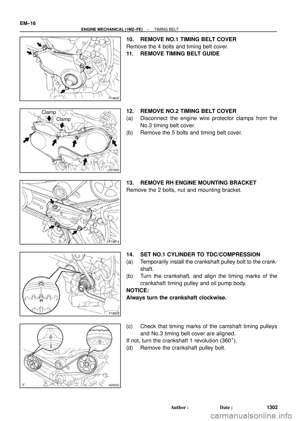
10. REMOVE NO.1 TIMING BELT COVER
Remove the 4 bolts and timing belt cover.
11. REMOVE TIMING BELT GUIDE
12. REMOVE NO.2 TIMING BELT COVER
(a) Disconnect the engine wire protector clamps from the
No.3 timing belt cover.
(b) Remove the 5 bolts and timing belt cover.
13. REMOVE RH ENGINE MOUNTING BRACKET
Remove the 2 bolts, nut and mounting bracket.
14. SET NO.1 CYLINDER TO TDC/COMPRESSION
(a) Temporarily install the crankshaft pulley bolt to the crank-
shaft.
(b) Turn the crankshaft, and align the timing marks of the
crankshaft timing pulley and oil pump body.
NOTICE:
Always turn the crankshaft clockwise.
(c) Check that timing marks of the camshaft timing pulleys
and No.3 timing belt cover are aligned.
If not, turn the crankshaft 1 revolution (360°).
(d) Remove the crankshaft pulley bolt.
Page 3530 of 4770

P18815
EM±24
± ENGINE MECHANICAL (1MZ±FE)TIMING BELT
1310 Author�: Date�:
10. CHECK VALVE TIMING
(a) Slowly turn the crankshaft 2 revolutions, and")
P18808
A05052
P12983
Length = 1,410 mm (55.51 in.)
P18815
EM±24
± ENGINE MECHANICAL (1MZ±FE)TIMING BELT
1310 Author�: Date�:
10. CHECK VALVE TIMING
(a) Slowly turn the crankshaft 2 revolutions, and align the tim-
ing marks of the crankshaft timing pulley and oil pump
body.
NOTICE:
Always turn the crankshaft clockwise.
(b) Check that the timing marks of the RH and LH timing pul-
leys with the timing marks of the No.3 timing belt cover as
shown in the illustration.
If the marks do not align, remove the timing belt and reinstall it.
(c) Remove the crankshaft pulley bolt.
11. INSTALL RH ENGINE MOUNTING BRACKET
Torque: 28 N´m (290 kgf´cm, 21 ft´lbf)
12. INSTALL NO.2 TIMING BELT COVER
(a) Check that the timing belt cover gasket has no cracks or
peeling, etc.
If the gasket has cracks or peeling, etc., replace it using these
steps:
�Using a screwdriver and gasket scraper, remove all
the old gasket material.
�Thoroughly clean all components to remove all the
loose material.
�Remove the backing paper from a new gasket and
install the gasket evenly to the part of the timing belt
cover shaded black in the illustration.
�After installing the gasket, press down on it so that
the adhesive firmly sticks to the timing belt cover.
(b) Install the timing belt cover with the 5 bolts.
Torque: 8.5 N´m (85 kgf´cm, 74 in.´lbf)
(c) Install the engine wire protector clamps to the No.3 timing
belt cover.
13. INSTALL TIMING BELT GUIDE
Install the timing belt guide, facing the cup side outward.
Page 3546 of 4770
P12797
SST
P12590
P12816
Recessed Head Bolt
8 mm Hexagon Wrench
Front EM±40
± ENGINE MECHANICAL (1MZ±FE)CYLINDER HEAD
1326 Author�: Date�:
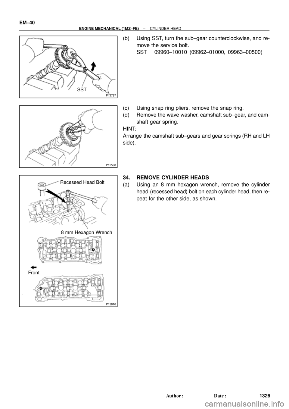
(b) Using SST, turn the sub±gear counterclockwise, and re-
move the service bolt.
SST 09960±10010 (09962±01000, 09963±00500)
(c) Using snap ring pliers, remove the snap ring.
(d) Remove the wave washer, camshaft sub±gear, and cam-
shaft gear spring.
HINT:
Arrange the camshaft sub±gears and gear springs (RH and LH
side).
34. REMOVE CYLINDER HEADS
(a) Using an 8 mm hexagon wrench, remove the cylinder
head (recessed head) bolt on each cylinder head, then re-
peat for the other side, as shown.
Page 3565 of 4770
CYLINDER HEAD
EM±59
1345 Author�: Date�:
(e) Using SST, align the hole")
P12974
SST
Main Gear
Sub±Gear
P12963
90°Exhaust
P12804
Exhaust
Front
A02008
Exhaust
Seal
Packing
± ENGINE MECHANICAL (1MZ±FE)CYLINDER HEAD
EM±59
1345 Author�: Date�:
(e) Using SST, align the holes of the camshaft main gear and
sub±gear by turning camshaft sub±gear counterclock-
wise, and temporarily install a service bolt.
SST 09960±10010 (09962±01000, 09963±00500)
(f) Align the gear teeth of the main gear and sub±gear, and
tighten the service bolt.
5. INSTALL CAMSHAFTS OF RH CYLINDER HEAD
NOTICE:
Since the thrust clearance of the camshaft is small, the
camshaft must be held level while it is being installed. If the
camshaft is not level, the portion of the cylinder head re-
ceiving the shaft thrust may crack or be damaged, causing
the camshaft to seize or break. To avoid this, the following
steps should be carried out.
(a) Install the exhaust camshaft.
(1) Apply new engine oil to the thrust portion and jour-
nal of the camshaft.
(2) Place the exhaust camshaft at 90° angle of timing
mark (2 dot marks) on the cylinder head.
(3) Apply MP grease to a new oil seal lip.
(4) Install the oil seal to the camshaft.
(5) Remove any old packing (FIPG) material.
(6) Apply seal packing to the No.1 bearing cap as
shown.
Seal packing: Part No. 08826±00080 or equivalent
Page 3614 of 4770
CYLINDER BLOCK
1394 Author�: Date�:
17. INSTALL ENGINE COOLANT DRAIN UNION
(a) Apply seal packing to 2 or 3")
P12477
Seal Packing
Z09223
Seal Width
3 ± 5 mmA
BA
B EM±108
± ENGINE MECHANICAL (1MZ±FE)CYLINDER BLOCK
1394 Author�: Date�:
17. INSTALL ENGINE COOLANT DRAIN UNION
(a) Apply seal packing to 2 or 3 threads.
Seal packing: Part No. 08826±00100 or equivalent
(b) Install the drain union.
Torque: 39 N´m (400 kgf´cm, 29 ft´lbf)
HINT:
After applying the specified torque, rotate the drain union clock-
wise until its drain port is facing downward.
18. INSTALL WATER SEAL PLATE
(a) Remove any old packing (FIPG) material and be careful
not to drop any oil on the contact surfaces of the seal plate
and cylinder block.
�Using a razor blade and gasket scraper, remove all
the old packing (FIPG) material from the gasket sur-
faces and sealing groove.
�Thoroughly clean all components to remove all the
loose material.
�Using a non±residue solvent, clean both sealing
surfaces.
(b) Apply seal packing to the seal plate as shown in the il-
lustration.
Seal packing: Part No. 08826±00100 or equivalent
�Install a nozzle that has been cut to a 3 ± 5 mm (0.12
± 0.20 in.) opening.
�Parts must be assembled within 3 minutes of ap-
plication. Otherwise the material must be removed
and reapplied.
�Immediately remove nozzle from the tube and rein-
stall cap.
(c) Install the seal plate with the 2 nuts.
Torque: 18 N´m (180 kgf´cm, 13 ft´lbf)
19. INSTALL OIL FILTER UNION
Torque: 30 N´m (310 kgf´cm, 22 ft´lbf)
20. INSTALL OIL FILTER (See page LU±15)
21. INSTALL OIL PUMP (See page LU±15)
22. INSTALL NO.1 OIL PAN (See page LU±15)
23. INSTALL OIL STRAINER (See page LU±15)
24. INSTALL NO.2 OIL PAN (See page LU±15)
25. INSTALL WATER PUMP (See page CO±8)
26. INSTALL WATER INLET HOUSING
(a) Remove any old packing (FIPG) material and be careful
not to drop any oil on the contact surfaces of the water in-
let housing and cylinder block.
�Using a razor blade and gasket scraper, remove all
the old packing (FIPG) material from the gasket sur-
faces and sealing grooves.
�Thoroughly clean all components to remove all the
loose material.
Page 3617 of 4770
EM0YU±01
A06653
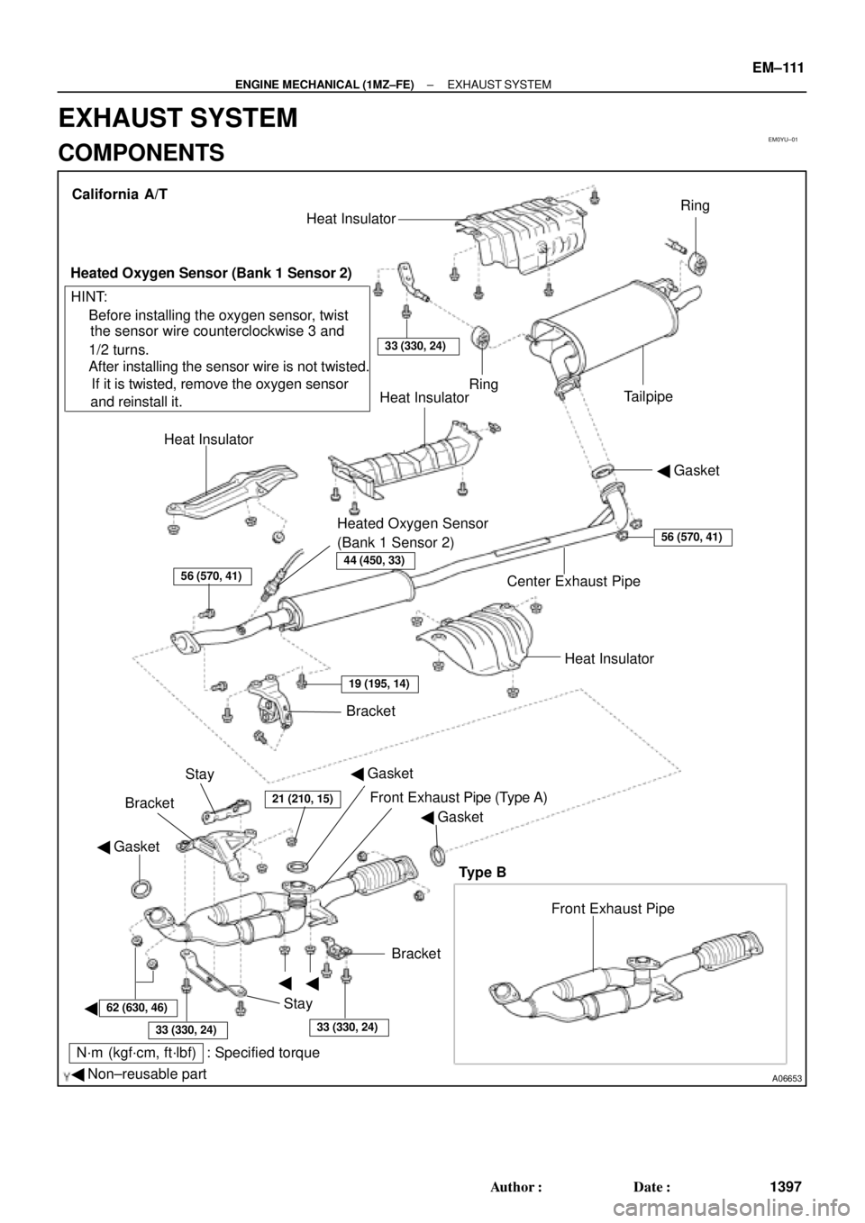
� Gasket
� Non±reusable part
N´m (kgf´cm, ft´lbf) : Specified torque� Gasket
�
�
�BracketFront Exhaust Pipe Bracket
StayHeat Insulator Center Exhaust Pipe� Gasket Heat InsulatorHeat Insulator
Heated Oxygen Sensor
(Bank 1 Sensor 2)TailpipeRing
Ring
33 (330, 24)
Heat Insulator
Heated Oxygen Sensor (Bank 1 Sensor 2)
� Before installing the oxygen sensor, twist
the sensor wire counterclockwise 3 and
1/2 turns.
If it is twisted, remove the oxygen sensor
and reinstall it. � After installing the sensor wire is not twisted. California A/T
Bracket
HINT:
56 (570, 41)
19 (195, 14)
21 (210, 15)
62 (630, 46)
33 (330, 24)33 (330, 24)
56 (570, 41)
Stay
Front Exhaust Pipe (Type A)
Type B
44 (450, 33)
� Gasket
± ENGINE MECHANICAL (1MZ±FE)EXHAUST SYSTEM
EM±111
1397 Author�: Date�:
EXHAUST SYSTEM
COMPONENTS
Page 3618 of 4770
A06652
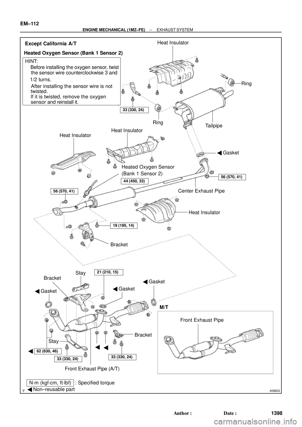
� Gasket
� Non±reusable part
N´m (kgf´cm, ft´lbf) : Specified torque� Gasket
�
�� Gasket
�Bracket
Stay
Front Exhaust Pipe (A/T) BracketBracket
Stay
21 (210, 15)
Heat Insulator Center Exhaust Pipe� Gasket Heat InsulatorHeat Insulator
Heated Oxygen Sensor
(Bank 1 Sensor 2)TailpipeRing
Ring
33 (330, 24)
Heat Insulator
Heated Oxygen Sensor (Bank 1 Sensor 2)
� Before installing the oxygen sensor, twist
the sensor wire counterclockwise 3 and
1/2 turns.
If it is twisted, remove the oxygen
sensor and reinstall it. � After installing the sensor wire is notExcept California A/T
HINT:
56 (570, 41)
19 (195, 14)
62 (630, 46)
33 (330, 24)33 (330, 24)
56 (570, 41)
twisted.
Front Exhaust Pipe
M/T
44 (450, 33)
EM±112
± ENGINE MECHANICAL (1MZ±FE)EXHAUST SYSTEM
1398 Author�: Date�:
Page 3639 of 4770
BO0MD±01
N21124
± BODYINSTRUMENT PANEL
BO±79
2437 Author�: Date�:
2001 CAMRY (RM819U)
DISASSEMBLY
1. REMOVE THESE PARTS:
(a) No.1 defroster nozzle garnish
(b) No.1 defroster nozzle
(c) RH side defroster duct nozzle
(d) No.1 side defroster duct nozzle
(e) No.1 heater duct to register
(f) No.2 heater duct to register
(g) No.2 register assembly
(h) No.3 register assembly
(i) No.1 register assembly
2. REMOVE INSTRUMENT PANEL WIRE HARNESS
Remove the 2 brackets, 8 clips and wire harness.
3. REMOVE INSTRUMENT PANEL CENTER BRACKET
4. REMOVE THESE PARTS:
(a) Clock unit
(b) Glove box light assembly