Page 4306 of 4770

SR06M±01
W03303
Matchmarks
W02655
Mark SR±16
± STEERINGTILT STEERING COLUMN
2111 Author�: Date�:
INSTALLATION
1. INSTALL STEERING COLUMN ASSEMBLY
(a) Torque the 4 column assembly set nuts.
Torque: 25 N´m (260 kgf´cm, 19 ft´lbf)
(b) Connect the connectors.
2. INSTALL INTERMEDIATE SHAFT ASSEMBLY
Torque the bolt.
Torque: 35 N´m (360 kgf´cm, 26 ft´lbf)
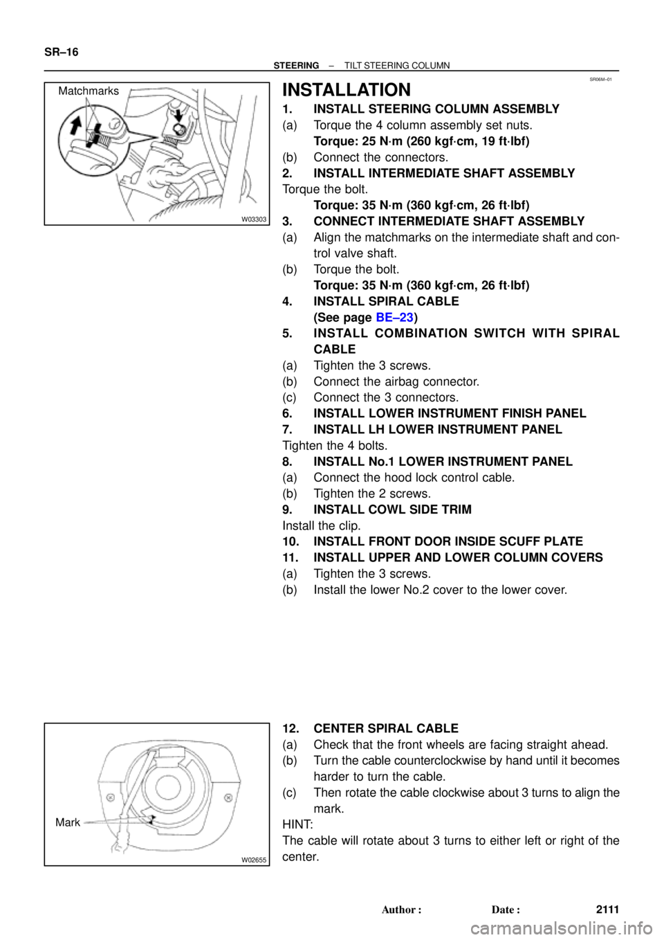
3. CONNECT INTERMEDIATE SHAFT ASSEMBLY
(a) Align the matchmarks on the intermediate shaft and con-
trol valve shaft.
(b) Torque the bolt.
Torque: 35 N´m (360 kgf´cm, 26 ft´lbf)
4. INSTALL SPIRAL CABLE
(See page BE±23)
5. INSTALL COMBINATION SWITCH WITH SPIRAL
CABLE
(a) Tighten the 3 screws.
(b) Connect the airbag connector.
(c) Connect the 3 connectors.
6. INSTALL LOWER INSTRUMENT FINISH PANEL
7. INSTALL LH LOWER INSTRUMENT PANEL
Tighten the 4 bolts.
8. INSTALL No.1 LOWER INSTRUMENT PANEL
(a) Connect the hood lock control cable.
(b) Tighten the 2 screws.
9. INSTALL COWL SIDE TRIM
Install the clip.
10. INSTALL FRONT DOOR INSIDE SCUFF PLATE
11. INSTALL UPPER AND LOWER COLUMN COVERS
(a) Tighten the 3 screws.
(b) Install the lower No.2 cover to the lower cover.
12. CENTER SPIRAL CABLE
(a) Check that the front wheels are facing straight ahead.
(b) Turn the cable counterclockwise by hand until it becomes
harder to turn the cable.
(c) Then rotate the cable clockwise about 3 turns to align the
mark.
HINT:
The cable will rotate about 3 turns to either left or right of the
center.
Page 4327 of 4770

R11554
Vinyl Tape
Shop RagPress
R11649
Matchmarks
R11650
R11651
Cylinder End
StopperWire
SST
± STEERINGPOWER STEERING GEAR
SR±37
2132 Author�: Date�:
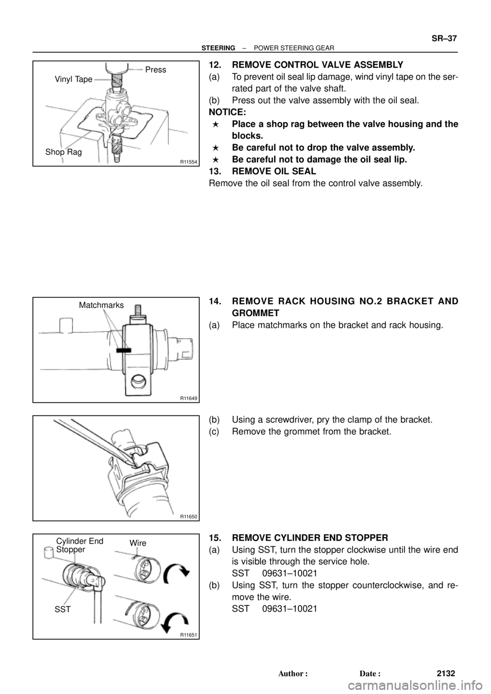
12. REMOVE CONTROL VALVE ASSEMBLY
(a) To prevent oil seal lip damage, wind vinyl tape on the ser-
rated part of the valve shaft.
(b) Press out the valve assembly with the oil seal.
NOTICE:
�Place a shop rag between the valve housing and the
blocks.
�Be careful not to drop the valve assembly.
�Be careful not to damage the oil seal lip.
13. REMOVE OIL SEAL
Remove the oil seal from the control valve assembly.
14. REMOVE RACK HOUSING NO.2 BRACKET AND
GROMMET
(a) Place matchmarks on the bracket and rack housing.
(b) Using a screwdriver, pry the clamp of the bracket.
(c) Remove the grommet from the bracket.
15. REMOVE CYLINDER END STOPPER
(a) Using SST, turn the stopper clockwise until the wire end
is visible through the service hole.
SST 09631±10021
(b) Using SST, turn the stopper counterclockwise, and re-
move the wire.
SST 09631±10021
Page 4334 of 4770

R11656
SST
Wire
Cylinder End
Stopper
R00662
SST
R11657
R11658
R11575
Vinyl Tape SR±44
± STEERINGPOWER STEERING GEAR
2139 Author�: Date�:
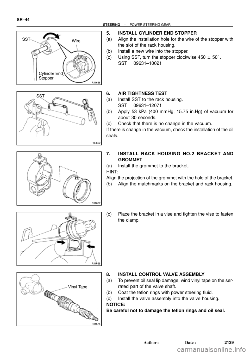
5. INSTALL CYLINDER END STOPPER
(a) Align the installation hole for the wire of the stopper with
the slot of the rack housing.
(b) Install a new wire into the stopper.
(c) Using SST, turn the stopper clockwise 450 ± 50°.
SST 09631±10021
6. AIR TIGHTNESS TEST
(a) Install SST to the rack housing.
SST 09631±12071
(b) Apply 53 kPa (400 mmHg, 15.75 in.Hg) of vacuum for
about 30 seconds.
(c) Check that there is no change in the vacuum.
If there is change in the vacuum, check the installation of the oil
seals.
7. INSTALL RACK HOUSING NO.2 BRACKET AND
GROMMET
(a) Install the grommet to the bracket.
HINT:
Align the projection of the grommet with the hole of the bracket.
(b) Align the matchmarks on the bracket and rack housing.
(c) Place the bracket in a vise and tighten the vise to fasten
the clamp.
8. INSTALL CONTROL VALVE ASSEMBLY
(a) To prevent oil seal lip damage, wind vinyl tape on the ser-
rated part of the valve shaft.
(b) Coat the teflon rings with power steering fluid.
(c) Install the valve assembly into the valve housing.
NOTICE:
Be careful not to damage the teflon rings and oil seal.
Page 4434 of 4770

RS3000 TVIP PROGRAMMING CHANGES FOR GBS ± AX006±99 April 23, 1999
Page 2 of 2
When performing the RS3000 System Test, check the Glass Breakage Sensor sensitivity
as follows:
1. Press and release the Remote Control's top button to arm the system.
2. Wait two seconds.
3. With the tip of the ignition key (or striker tool), softly tap the center of the driver's door
window glass.
�If the system is triggered (horn sounds for 20 seconds), the sensitivity must be
adjusted. Turn the Glass Breakage Sensor ECU's adjustment screw clockwise
one notch, and repeat this step again.
4. If the system is not triggered, repeat the glass tapping with moderate force.
�The system should trigger when the glass is tapped with moderate force. If it is
not triggered, turn the Glass Breakage Sensor ECU's adjustment screw clockwise
one notch, and repeat this step again.
CAUTION:
Use caution when performing the step above. Do not tap the window glass with too
much force, or the glass may crack or break. Use extra caution when the temperature
is extremely cold.
NOTE:
The Owner's Guide included in the RS3000 Base Kit is changed to reflect the
(GBS logic) improvement. There is no change to the GBS ECU itself. Repair
Procedure