Page 1211 of 4592

S05390
No.1 Cooling
Fan Relay
CO040±03
S04975
Ohmmeter
ContinuityContinuity
Ohmmeter 1
3
24
S04976
Ohmmeter
No Continuity
1
3
24
Battery
S05387
No.2 Cooling
Fan Relay
S04972
Ohmmeter
Ohmmeter Ohmmeter
No Continuity 1
32 4
5
Continuity
± COOLING (1MZ±FE)COOLING FAN RELAY
CO±37
1645 Author�: Date�:
COOLING FAN RELAY
INSPECTION
1. REMOVE RELAY BOX COVER
2. INSPECT NO.1 COOLING FAN RELAY
(a) Remove the No.1 cooling fan relay. (Marking: FAN NO.1)
(b) Inspect the No.1 cooling fan relay continuity.
(1) Using an ohmmeter, check that there is continuity
between terminals 1 and 2.
If there is no continuity, replace the relay.
(2) Check that there is continuity between terminals 3
and 4.
If there is no continuity, replace the relay.
(c) Inspect the No.1 cooling fan relay operation.
(1) Apply battery positive voltage across terminals 1
and 2.
(2) Using an ohmmeter, check that there is no continu-
ity between terminals 3 and 4.
If there is continuity, replace the relay.
(d) Reinstall the No.1 cooling fan relay.
3. INSPECT NO.2 COOLING FAN RELAY
(a) Remove the No.2 cooling fan relay. (Marking: FAN NO.2)
(b) Inspect the No.2 cooling fan relay continuity.
(1) Using an ohmmeter, check that there is continuity
between terminals 1 and 2.
If there is no continuity, replace the relay.
(2) Check that there is continuity between terminals 3
and 4.
If there is no continuity, replace the relay.
(3) Check that there is no continuity between terminals
3 and 5.
If there is continuity, replace the relay.
Page 1212 of 4592

S04971
OhmmeterBattery
No ContinuityOhmmeter
Continuity 1
32 4
5
S05388
No.3 Cooling
Fan Relay
S04970
Ohmmeter
No ContinuityOhmmeter
1
32
5 Continuity
S04969
Ohmmeter
1
32
5
Continuity Battery CO±38
± COOLING (1MZ±FE)COOLING FAN RELAY
1646 Author�: Date�:
(c) Inspect the No.2 cooling fan relay operation.
(1) Apply battery positive voltage across terminals 1
and 2.
(2) Using an ohmmeter, check that there is no continu-
ity between terminals 3 and 4.
If there is continuity, replace the relay.
(d) Reinstall the No.2 cooling fan relay.
4. INSPECT NO.3 COOLING FAN RELAY
(a) Remove the No.3 cooling fan relay. (Marking: FAN NO.3)
(b) Inspect the No.3 cooling fan relay continuity.
(1) Using an ohmmeter, check that there is continuity
between terminals 1 and 2.
If there is mo continuity, replace the relay.
(2) Check that there is no continuity between terminals
3 and 5.
If there is continuity, replace the relay.
(c) Inspect the No.3 cooling fan relay operation.
(1) Apply battery positive voltage across terminals 1
and 2.
(2) Using an ohmmeter, check that there is continuity
between terminals 3 and 5.
If there is no continuity, replace the relay.
(d) Reinstall the No.3 cooling fan relay.
5. REINSTALL RELAY BOX COVER
Page 1240 of 4592

263 Author�: Date�:
PROBLEM SYMPTOMS TABLE
SymptomSuspect AreaSee page
Engine does not crank (Does not start)1. Starter
2. starter relayST±2
ST±20
No i")
DI00L±03
DI±28
± DIAGNOSTICSENGINE (5S±FE)
263 Author�: Date�:
PROBLEM SYMPTOMS TABLE
SymptomSuspect AreaSee page
Engine does not crank (Does not start)1. Starter
2. starter relayST±2
ST±20
No initial combustion (Does not start)
1. ECM power source circuit
2. Fuel pump control circuit
3. Engine control module (ECM)DI±179
DI±183
IN±31
No complete combustion (Does not start)1. Fuel pump control circuitDI±183
Engine cranks normally (Difficult to start)
1. Starter signal circuit
2. Fuel pump control circuit
3. CompressionDI±176
DI±183
EM±3
Cold engine (Difficult to start)1. Starter signal circuit
2. Fuel pump control circuitDI±176
DI±183
Hot engine (Difficult to start)1. Starter signal circuit
2. Fuel pump control circuitDI±176
DI±183
High engine idle speed (Poor idling)1. A/C switch circuit
2. ECM power source circuitAC±84
DI±179
Low engine idle speed (Poor idling)1. A/C switch circuit
2. Fuel pump control circuit AC±84
DI±183
Rough idling (Poor idling)1. Compression
2. Fuel pump control circuitEM±3
DI±183
Hunting (Poor idling)1. ECM power source circuit
2. Fuel pump control circuitDI±179
DI±183
Hesitation/Poor acceleration (Poor driveability)1. Fuel pump control circuit
2. A/T faulty DI±183
DI±405
Surging (Poor driveability)1. Fuel pump control circuitDI±183
Soon after starting (Engine stall)1. Fuel pump control circuitDI±183
During A/C operation (Engine stall)1. A/C switch circuit
2. Engine control module (ECM) AC±84
IN±31
A/C switch indicatior blinking1. A/C Compressor lock sensor circuit
2. A/C Evaporator temp. sensor circuitDI±190
DI±192
Unable to refuel/ Difficult to refuel1. ORVR systemEC±6
Page 1268 of 4592

A03597
B±Y
FL
Block47
EFI
IGN
14 2
4 EFI
Relay
21
53
B±Y
BR
3
12 B
B
1
24 3 9
II3
J/CB
W±R
P±B
W
BG
P±B 56
2
5
1K
14
HT2 21 O 1W
E9E8
E9 E8
MAIN FLE8 1B
B 1ECMAF�
OX2 HTAF
AF� 1K
2F
E03 E1E04 A/F
Sensor
Engine Room R/B No.2
B±YJ19 J/C
2
1
II2II3
II3
EB
Heated
Oxygen
Sensor
(Bank 1
Sensor 2)
EC
Instrument
Panel J/B7
3 5
6
7
2L 2A
F611
F4
B±G
Battery B±R
2K
2J
W±B
3.3V
3.0V
AM2 B
W±R
J27
*1: w/o Immobiliser
*2: w/ Immobiliser
(*1)
(*2)
to Analog±Digital
Converter
E914 E8 13
(*1) (*2) J27
B±Y
B±Y
IG Switch
B±R
*3: California
(*6) (*3) (*6) (*3)
(*1)
2
MREL
E107
(*2)
EE
J27 J27
J/C
B BB±Y
II4
6
B±W(*2)
B±W(*2)
*5:TMC Made
*6:TMMK Made
L(*5)
(*3)
B±W(*5)
(*3)
BR
*4: Except California
DI±56
± DIAGNOSTICSENGINE (5S±FE)
291 Author�: Date�:
HINT:
�After confirming DTC P0125, use the OBD II scan tool or TOYOTA hand-held tester to confirm voltage
output of A/F sensor from the CURRENT DATA.
�The ECM controls the voltage of AF� and AF� terminals of ECM to the fixed voltage. Therefore, it
is impossible to confirm the A/F sensor output voltage without OBD II scan tool or TOYOTA hand±held
tester.
�OBD II scan tool (excluding TOYOTA hand±held tester) displays the one fifth of the A/F sensor output
voltage which is displayed on the TOYOTA hand±held tester.
WIRING DIAGRAM
INSPECTION PROCEDURE
HINT:
�If the vehicle run out fuel, the air±fuel ratio is LEAN and DTC P0125 will be recorded.
The MIL then comes on.
�Read freeze frame data using TOYOTA hand±held tester or OBD II scan tool. Because freeze frame
records the engine conditions when the malfunction is detected, when troubleshooting it is useful for
determining whether the vehicle was running or stopped, the engine warmed up or not, the air±fuel
ratio lean or rich, etc. at the time of the malfunction.
Page 1274 of 4592

A03596
B±Y
Engine Room R/B No.2
Battery
IG Switch17
EFI
W±R7 7 2
5 EFI
Relay
5 3
24
W±BP±B
BR14 2314 2
3
9
II3
B±Y
B±Y
W±R B
W B±Y
B
BR6
128
25 1 2K
21 1KE8
E9
AM2
E8
E9ECM
OX1
OX2 HT1
HT2 1K 2JB±Y
J/C
1B
2F5 B±R
1W
Heated
Oxygen
Sensor
(Bank 1
Sensor 1)
II2
II3Heated
Oxygen
Sensor
(Bank 1
Sensor 2)E03
B J19 J/C
BBB
3
MAIN 2A 2L 4
F4 F6FL
Block
B±GP±B
J27 J27
1
EB
EC
6
IGN
E03 L±YE1
E1 Instrument
Panel J/B
11
B±R
*1: w/o Immobiliser
*2: w/ Immobiliser
(*2) (*1)
E9 14E8 E9 E85
1
13
(*2) (*1)(*1) (*2)(*1) (*2) (*3)
EB±Y
(*3) (*3)
(*1)FL
*3: Except California BII3
E
B±YJ27 J27
MREL
E10 B±W
II4
6
B±W(*2)
(*3)
7(*2)(*2)
BR BR
DI±62
± DIAGNOSTICSENGINE (5S±FE)
297 Author�: Date�:
HINT:
After confirming DTC P0125, use the OBD II scan tool or TOYOTA hand-held tester to confirm voltage output
of the heated oxygen sensor (bank 1 sensor 1) from the CURRENT DATA.
If voltage output of the heated oxygen sensor (bank 1 sensor 1) is 0 V, heated oxygen sensor (bank 1 sensor
1) circuit may be open or short.
WIRING DIAGRAM
INSPECTION PROCEDURE
HINT:
�If the vehicle run out fuel, the air±fuel ratio is LEAN and DTC P0125 will be recorded.
The MIL then comes on.
�Read freeze frame data using TOYOTA hand±held tester or OBD II scan tool. Because freeze frame
records the engine conditions when the malfunction is detected, when troubleshooting it is useful for
determining whether the vehicle was running or stopped, the engine warmed up or not, the air±fuel
ratio lean or rich, etc. at the time of the malfunction.
Page 1288 of 4592
A03014A03415
ON
HT1
HT2
w/o Immobiliser
w/ Immobiliser
HT1
HT2
DI±76
± DIAGNOSTICSENGINE (5S±FE)
311 Author�: Date�:
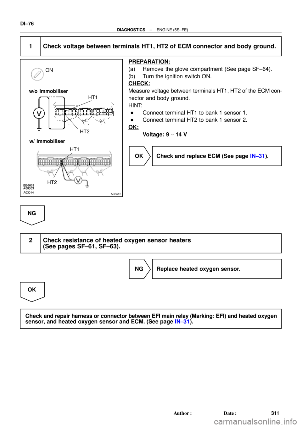
1 Check voltage between terminals HT1, HT2 of ECM connector and body ground.
PREPARATION:
(a) Remove the glove compartment (See page SF±64).
(b) Turn the ignition switch ON.
CHECK:
Measure voltage between terminals HT1, HT2 of the ECM con-
nector and body ground.
HINT:
�Connect terminal HT1 to bank 1 sensor 1.
�Connect terminal HT2 to bank 1 sensor 2.
OK:
Voltage: 9 ~ 14 V
OK Check and replace ECM (See page IN±31).
NG
2 Check resistance of heated oxygen sensor heaters
(See pages SF±61, SF±63).
NG Replace heated oxygen sensor.
OK
Check and repair harness or connector between EFI main relay (Marking: EFI) and heated oxygen
sensor, and heated oxygen sensor and ECM. (See page IN±31).
Page 1318 of 4592
A07551
ECM
J19
J/C
7 From
Battery
B
213
EFI Relay VSV
for EGR
21P-B23
E9EGR
E01
2K2
2J EFI
II4
Engine Room J/B No.2 1B
B-W 9
B-Y
B
2AB-Y
II3
EB
W-B
2F4
6
B-W B-YE815
MREL E107 (*1) (*2)
(*2)
*1: w/o Immobiliser
*2: w/ Immobiliser(*2) (*2)
5B-Y
(*1)From
Ignition SW DI±106
± DIAGNOSTICSENGINE (5S±FE)
341 Author�: Date�:
WIRING DIAGRAM
Page 1335 of 4592

A07552
3
2
1Y
P
BRECM
1
1
7
9
22 J19
J/C
8
E8
E8
EBE8
E01 E9
E8
EJ/C
J28
J27
10
1V
6
2F From
BatteryB±Y VSV
for EVAP
2V±W
VSV for Vapor
Pressure
Sensor
9
Engine Room J/B No.2 B±Y
EFI II3
53
B±Y
VC
PTNK
E2
EVP
TPC5 V
E1
E01
2J 2A
2K
2
*1: w/o Immobiliser
*2: w/ Immobiliser
(*1) (*2)
MREL(*2)
E8
8
E9
3
E8
16
E10
7 Y Y Vapor Pressure Sensor
P P
BR BR
E
ID1 ID1
1
V V
B±Y
B±W B±W
II4 II4
5
ID1
ID1
ID1
6 5
237
8
II4 II4
II2
(*1) (*2)(*1) (*2)
W±B
B±Y12
BB
B±Y
12
7 4
EFI Relay J27 J27B±Y
B
BJ/C
(*2) (*2)
B±R(*1)From
Ignition SW
± DIAGNOSTICSENGINE (5S±FE)
DI±123
358 Author�: Date�:
WIRING DIAGRAM
INSPECTION PROCEDURE
HINT:
�If DTC P0441 (Evaporative Emission Control System Incorrect Purge Flow), P0446 (Evaporative
Emission Control System Vent Control Malfunction), P0450 (Evaporative Emission Control System
Pressure Sensor Malfunction) or P0451 is output after DTC P0440 (Evaporative Emission Control Sys-
tem Malfunction), first troubleshoot DTC P0441, P0446, P0450 or P0451. If no malfunction is detected,
troubleshoot DTC P0440 next.
�Ask the customer whether, after the MIL came on, the customer found the fuel tank cap loose and tight-
ened it. Also ask the customer whether the fuel tank cap was loose when refuelling. If the fuel tank cap
was not loose, it was the cause of the DTC. If the fuel tank cap was not loose or if the customer was
not sure if it was loose, troubleshoot according to the following procedure.
�Read freeze frame data using TOYOTA hand±held tester or OBD II scan tool. Because freeze frame
records the engine conditions when the malfunction is detected, when troubleshooting it is useful for
determining whether the vehicle was running or stopped, the engine warmed up or not, the air±fuel
ratio lean or rich, etc. at the time of the malfunction.
�When the ENGINE RUN TIME in the freeze frame data is less than 200 seconds, carefully check the
VSV for EVAP, charcoal canister and vapor pressure sensor.
 (*2)
(*2)
*1: w")