Page 1396 of 4592
A07555
Battery
EFI
AM2
123
3 1J
B2A
2J Instrument Panel J/B
B
1B 1W
37
1 5
IG Switch
1
B±W
B±RST RelayEFI Relay
5
6
2 3
1 11 410
4
5 4
5
A 2B STARTER
(M/T)
B±G
II23
B±W
II211
Starter
Park/Neutral
Position Switch
Clutch Start
Switch
5 7
B±R Engine Room J/B No.2
2C
2F IGN
FL Block1
2D1
BMAIN
B±O (*3) W±B
GR (*2)
10B
C
1
CIR
OPN
Relay
L±B
IGG±R
W±B
14 2L
E7FCECM
E01
1
S1S2
Engine Room R/B
No.1
2
J40
J/C
G±RL±B
5 93
Fuel
Pump
L±B
R
EB B±R
GR
W±R
B±W
B±WB±O (*3)(A/T)
BL
J/CB±R
J8
2K
J7
B
1 1 1
B 1K
1K
1K
8 7
6
EB1 4
J29
J/C J11
J/CF6 1 W±R
MAIN
FL4
5 2K
2
B±R (*4)
*1: w/ Immobiliser(*1)
MREL
E107 B±W
B
B
B±WII4
6
F41
GR (*2)
*2: TMC Made
*3: TMMK Made A
(*1)
(*1)
GR (*2)
B±O (*3)(M/T)
*4: w/o Immobiliser
EB1 B±R
B±R (*1)
B±R (*4)
IK17
55
7
ID1
7 W±B
W±B
DI±184
± DIAGNOSTICSENGINE (5S±FE)
419 Author�: Date�:
WIRING DIAGRAM
Page 1397 of 4592
± DIAGNOSTICSENGINE (5S±FE)
DI±185
420 Author�: Date�:
INSPECTION PROCEDURE
TOYOTA hand±held tester:
1 Connect TOYOTA hand±held tester, and check operation of fuel pump
(See page DI±3).
OK Proceed to next circuit inspection shown on
problem symptoms table (See page DI±28).
NG
2 Check for ECM power source circuit (See page DI±179).
NG Repair or replace.
OK
3 Check circuit opening relay (Marking: CIR OPN) (See page SF±41).
NG Replace circuit opening relay.
OK
Page 1398 of 4592
A03029A03450
FC (+) ON
w/o Immobiliser
w/ Immobiliser
FC (+)
DI±186
± DIAGNOSTICSENGINE (5S±FE)
421 Author�: Date�:
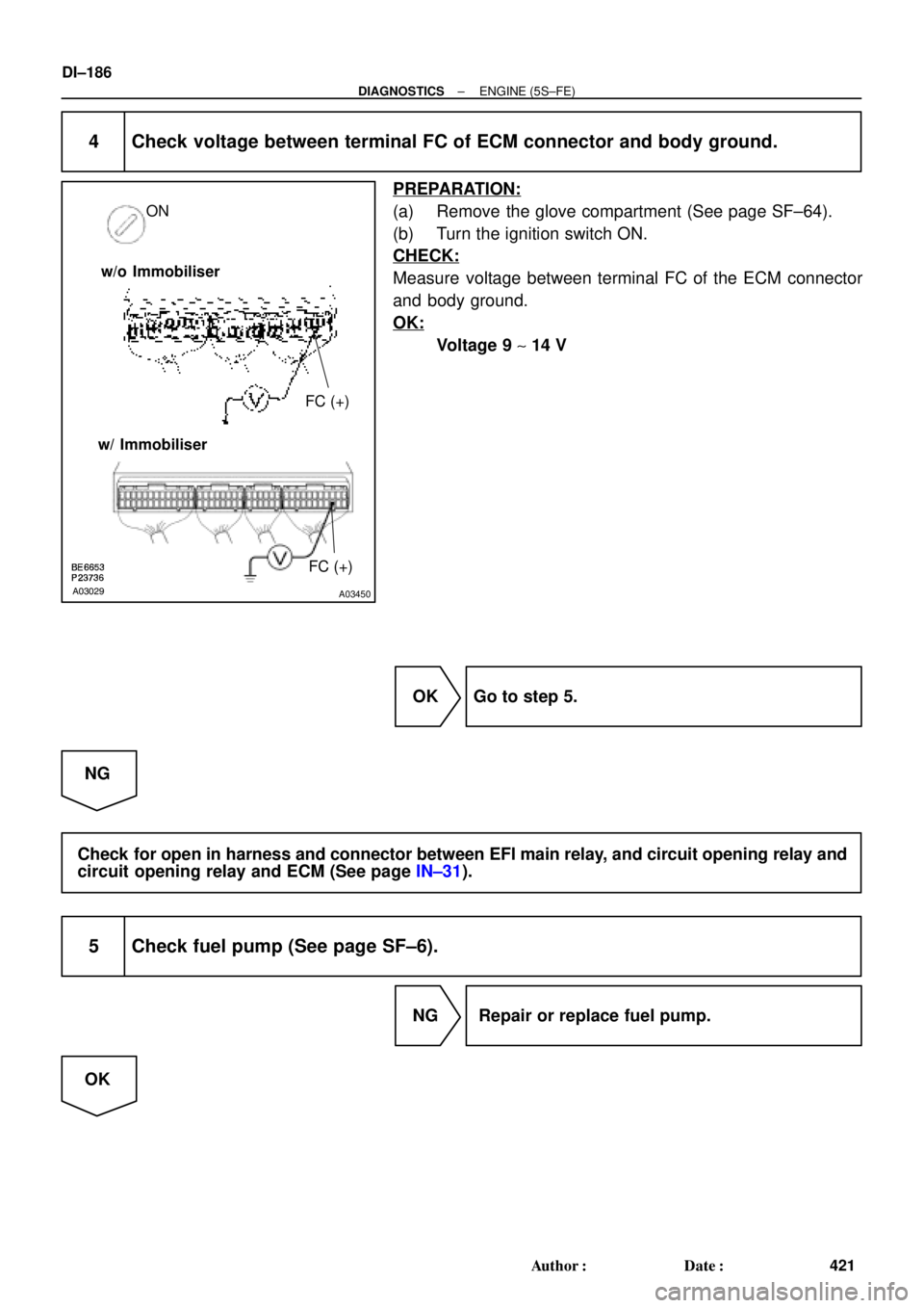
4 Check voltage between terminal FC of ECM connector and body ground.
PREPARATION:
(a) Remove the glove compartment (See page SF±64).
(b) Turn the ignition switch ON.
CHECK:
Measure voltage between terminal FC of the ECM connector
and body ground.
OK:
Voltage 9 ~ 14 V
OK Go to step 5.
NG
Check for open in harness and connector between EFI main relay, and circuit opening relay and
circuit opening relay and ECM (See page IN±31).
5 Check fuel pump (See page SF±6).
NG Repair or replace fuel pump.
OK
Page 1399 of 4592
A03030A03451
ON
FC
OFFON
Fuel Inlet Hose
FC
OFF
ON w/o Immobiliser
w/ Immobiliser
± DIAGNOSTICSENGINE (5S±FE)
DI±187
422 Author�: Date�:
6 Check for open in harness and connector between circuit opening relay (Mark-
ing: CIR OPN) and fuel pump, and fuel pump and body ground
(See page IN±31).
NG Repair or replace harness or connector.
OK
Check and replace ECM (See page IN±31).
OBD II scan tool (excluding TOYOTA hand±held tester):
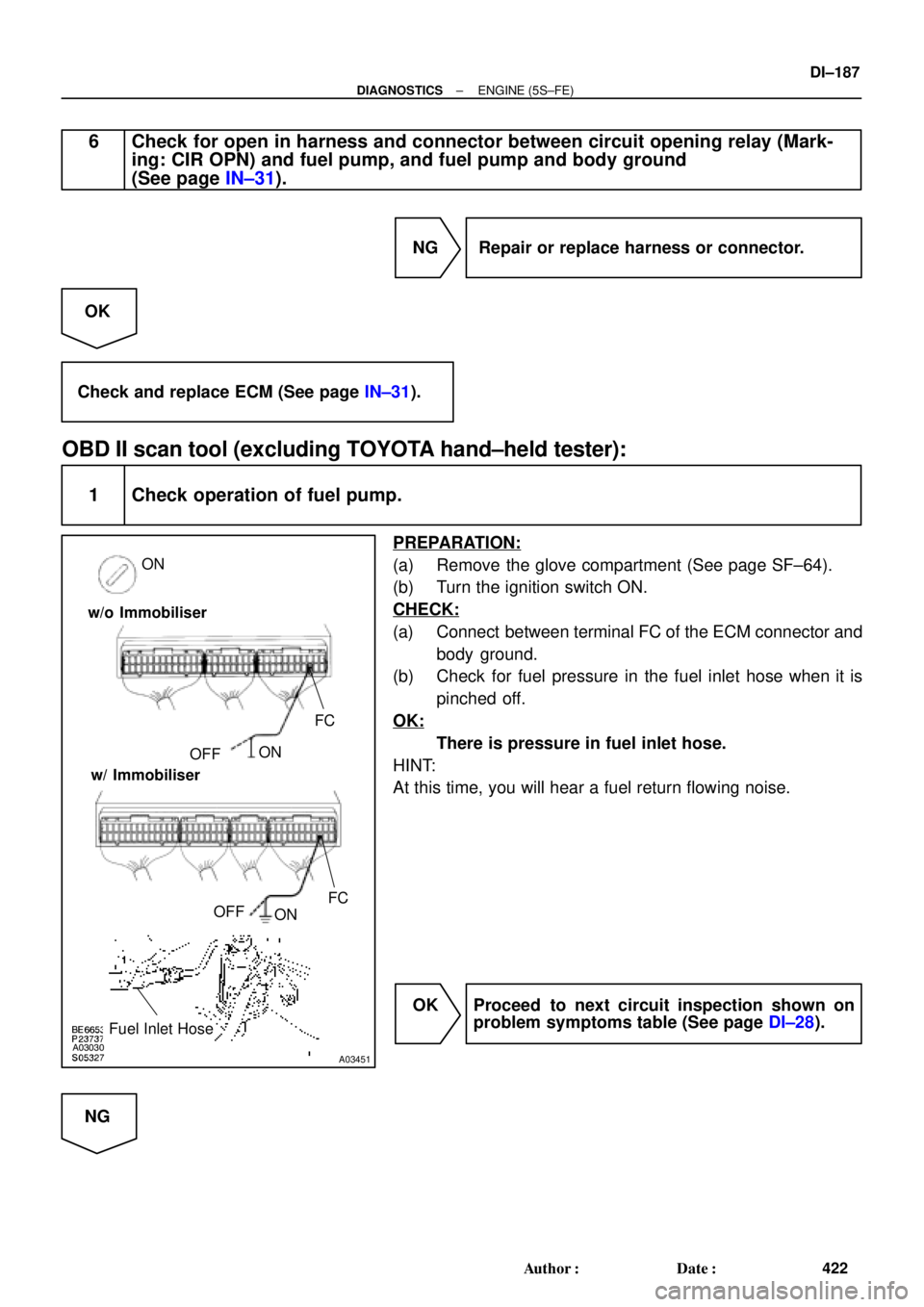
1 Check operation of fuel pump.
PREPARATION:
(a) Remove the glove compartment (See page SF±64).
(b) Turn the ignition switch ON.
CHECK:
(a) Connect between terminal FC of the ECM connector and
body ground.
(b) Check for fuel pressure in the fuel inlet hose when it is
pinched off.
OK:
There is pressure in fuel inlet hose.
HINT:
At this time, you will hear a fuel return flowing noise.
OK Proceed to next circuit inspection shown on
problem symptoms table (See page DI±28).
NG
Page 1400 of 4592
DI±188
± DIAGNOSTICSENGINE (5S±FE)
423 Author�: Date�:
2 Check for ECM power source circuit (See page DI±179).
NG Repair or replace.
OK
3 Check circuit opening relay (Marking: CIR OPN) (See page SF±41).
NG Replace circuit opening relay.
OK
4 Check voltage between terminal FC of ECM connector and body ground
(See page DI±183, step 4).
OK Go to step 5.
NG
Check for open in harness and connector between EFI main relay and circuit opening relay, and
circuit opening relay and ECM (See page IN±31).
5 Check fuel pump (See page SF±6).
NG Repair or replace fuel pump.
OK
Page 1401 of 4592
± DIAGNOSTICSENGINE (5S±FE)
DI±189
424 Author�: Date�:
6 Check for open in harness and connector between circuit opening relay (Mark-
ing: CIR OPN) and fuel pump, and fuel pump and body ground
(See page IN±31).
NG Repair or replace harness or connector.
OK
Check and replace ECM (See page IN±31).
Page 1433 of 4592

DI±221
456 Author�: Date�:
PROBLEM SYMPTOMS TABLE
SymptomSuspect AreaSee page
Engine does not crank (Does not start)1. Starter
2. Starter relayST±18
ST±20")
DI07E±06
± DIAGNOSTICSENGINE (1MZ±FE)
DI±221
456 Author�: Date�:
PROBLEM SYMPTOMS TABLE
SymptomSuspect AreaSee page
Engine does not crank (Does not start)1. Starter
2. Starter relayST±18
ST±20
No initial combustion (Does not start)
1. ECM power source circuit
2. Fuel pump control circuit
3. Engine control module (ECM)DI±369
DI±374
IN±31
No complete combustion (Does not start)1. Fuel pump control circuitDI±374
Engine cranks normally (Difficult to start)
1. Starter signal circuit
2. Fuel pump control circuit
3. CompressionDI±384
DI±374
EM±3
Cold engine (Difficult to start)1. Starter signal circuit
2. Fuel pump control circuitDI±384
DI±374
Hot engine (Difficult to start)1. Starter signal circuit
2. Fuel pump control circuitDI±384
DI±374
High engine idle speed (Poor idling)1. A/C signal circuit (Compressor Circuit)
2. ECM power source circuitAC±88
DI±369
Low engine idle speed (Poor idling)1. A/C signal circuit (Compressor Circuit)
2. Fuel pump control circuitAC±88
DI±374
Rough idling (Poor idling)1. Compression
2. Fuel pump control circuitEM±3
DI±374
Hunting (Poor idling)1. ECM power source circuit
2. Fuel pump control circuitDI±369
DI±374
Hesitation/Poor acceleration (Poor driveability)1. Fuel pump control circuit
2. A/T faultyDI±374
DI±453
Surging (Poor driveability)1. Fuel pump control circuitDI±374
Soon after starting (Engine stall)1. Fuel pump control circuitDI±374
During A/C operation (Engine stall)1. A/C signal circuit (Compressor Circuit)
2. Engine control module (ECM)AC±88
IN±31
Unable to refuel/Difficult to refuel1. ORVR systemEC±6
Page 1435 of 4592
A06156
Engine Room J/B
EFI Relay
Junction
Connector
J20
Junction
Connector EFI
2A
2K2J
2C B
EB
7 1
2
5
13
2
F9
F4
11
B±G
Mass Air
Flow Meter
B±Y
B±Y
B±Y
R
R±BECM
E2GVG
E2 P 5B
B
9
4 A A
5
3
8
W±B
E10 B±W
E7 10
19
MRELB+ E10 Junction
ConnectorJ35 J36
A
A
B±W
Fusible
Link
Block
FL
MAIN
Battery
J27J28
II3
± DIAGNOSTICSENGINE (1MZ±FE)
DI±223
458 Author�: Date�:
WIRING DIAGRAM
INSPECTION PROCEDURE
HINT:
Read freeze frame data using TOYOTA hand±held tester or OBD II scan tool. Because freeze frame records
the engine conditions when the malfunction is detected, when troubleshooting it is useful for determining
whether the vehicle was running or stopped, the engine warmed up or not, the air±fuel ratio lean or rich, etc.
at the time of the malfunction.

B±G
II23
B±W
II211
Starter
Park/Neutral")