Page 4 of 4592
I01386
AC±4
± AIR CONDITIONINGAIR CONDITIONING SYSTEM
2486 Author�: Date�:
2. INSPECT REFRIGERANT PRESSURE WITH MAN-
IFOLD GAUGE SET
This is a method in which the trouble is located by using a man-
ifold gauge set. Read the manifold gauge pressure when the
these conditions are established.
Test conditions:
�Temperature at the air inlet with the switch set
at RECIRC is 30 ± 35 °C (86 ± 95 °F)
�Engine running at 1500 rpm
�Blower speed control switch at ºHIº position
�Temperature control dial on ºCOOLº position
HINT:
It should be noted that the gauge indications may vary slightly
due to ambient temperature conditions.
(1) Normally functioning refrigeration system.
Gauge reading:
Low pressure side:
0.15 ± 0.25 MPa (1.5 ± 2.5 kgf/cm
2)
High pressure side:
1.37 ± 1.57 MPa (14 ± 16 kgf/cm
2)
Page 15 of 4592

± AIR CONDITIONINGTROUBLESHOOTING
AC±15
2497 Author�: Date�:
Cool air comes out only at high engine rpm
1. Refrigerant volume
2. Drive belt
3. Magnetic clutch
4. Compressor
5. Condenser
6. Condenser fan
7. Receiver
8. Expansion valve
9. Evaporator
10.Thermistor
11. Refrigerant line
12.Pressure switch
13.*
1 ECM
*2 A/C amplifier
AC±3
AC±16
AC±16
AC±39
AC±52
AC±74
AC±49
AC±59
AC±30
AC±24
AC±21
AC±67
DI±218
AC±88
No engine idle±up when A/C switch ON
1. *1 ECM
*2 A/C amplifier
2. Wire harness
DI±218
AC±88
±
Blinking of A/C indicator
1. *1 ECM
*2 A/C amplifier
2. Thermistor
3. Compressor
DI±218
AC±88
AC±24
AC±39
A/C indicator does not lights up when turn mode switch to DEF.
position
1. A/C Fuse
2. Mode switch
3. A/C switch
4. *
1 ECM
*2 A/C amplifier
5. Wire harness
±
AC±84
AC±84
DI±218
AC±88
±
No warm air comes out
1. Engine coolant volume
2. A/C control assembly
3. Heater radiator±
AC±80
AC±57
No condenser fan operation
1. CDS FAN Fuse
2. Engine main relay
3. Cooling fan relay No. 1
4. Cooling fan relay No. 2
5. Cooling fan relay No. 3
6. Condenser fan motor
7. Pressure switch
8. *
1 Engine coolant temp. switch
*2 No. 1 Engine coolant temp. switch
9. *2No. 2 Engine coolant temp. switch
10.Wire harness
±
±
AC±72
AC±72
AC±72
AC±74
AC±67
AC±92
AC±92
AC±92
±
*1: 5S±FE Engine Models
*
2: 1MZ±FE Engine Models
Page 28 of 4592

I03838
SST
I03839
PushSST
Pull
SST
Release
Lever
I06919
Disconnect the tube
using hand
Screw
Driver
Tube
I06878
Correct Wrong
Gap
N20281
AC±28
± AIR CONDITIONINGAIR CONDITIONING UNIT
2510 Author�: Date�:
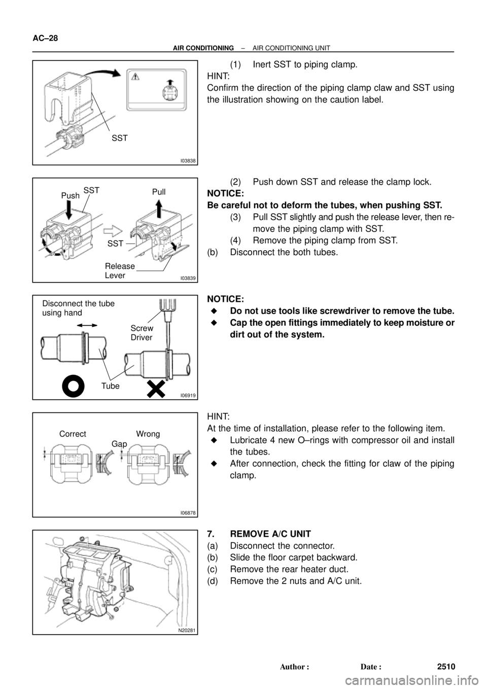
(1) Inert SST to piping clamp.
HINT:
Confirm the direction of the piping clamp claw and SST using
the illustration showing on the caution label.
(2) Push down SST and release the clamp lock.
NOTICE:
Be careful not to deform the tubes, when pushing SST.
(3) Pull SST slightly and push the release lever, then re-
move the piping clamp with SST.
(4) Remove the piping clamp from SST.
(b) Disconnect the both tubes.
NOTICE:
�Do not use tools like screwdriver to remove the tube.
�Cap the open fittings immediately to keep moisture or
dirt out of the system.
HINT:
At the time of installation, please refer to the following item.
�Lubricate 4 new O±rings with compressor oil and install
the tubes.
�After connection, check the fitting for claw of the piping
clamp.
7. REMOVE A/C UNIT
(a) Disconnect the connector.
(b) Slide the floor carpet backward.
(c) Remove the rear heater duct.
(d) Remove the 2 nuts and A/C unit.
Page 85 of 4592

AC0NG±02
N19466
ON OFF
2
1
N19484
ON
OFF
2
1 4
N19467
ON
OFF
N19464
M1
M2 AC±84
± AIR CONDITIONINGAIR CONDITIONING CONTROL ASSEMBLY
2566 Author�: Date�:
INSPECTION
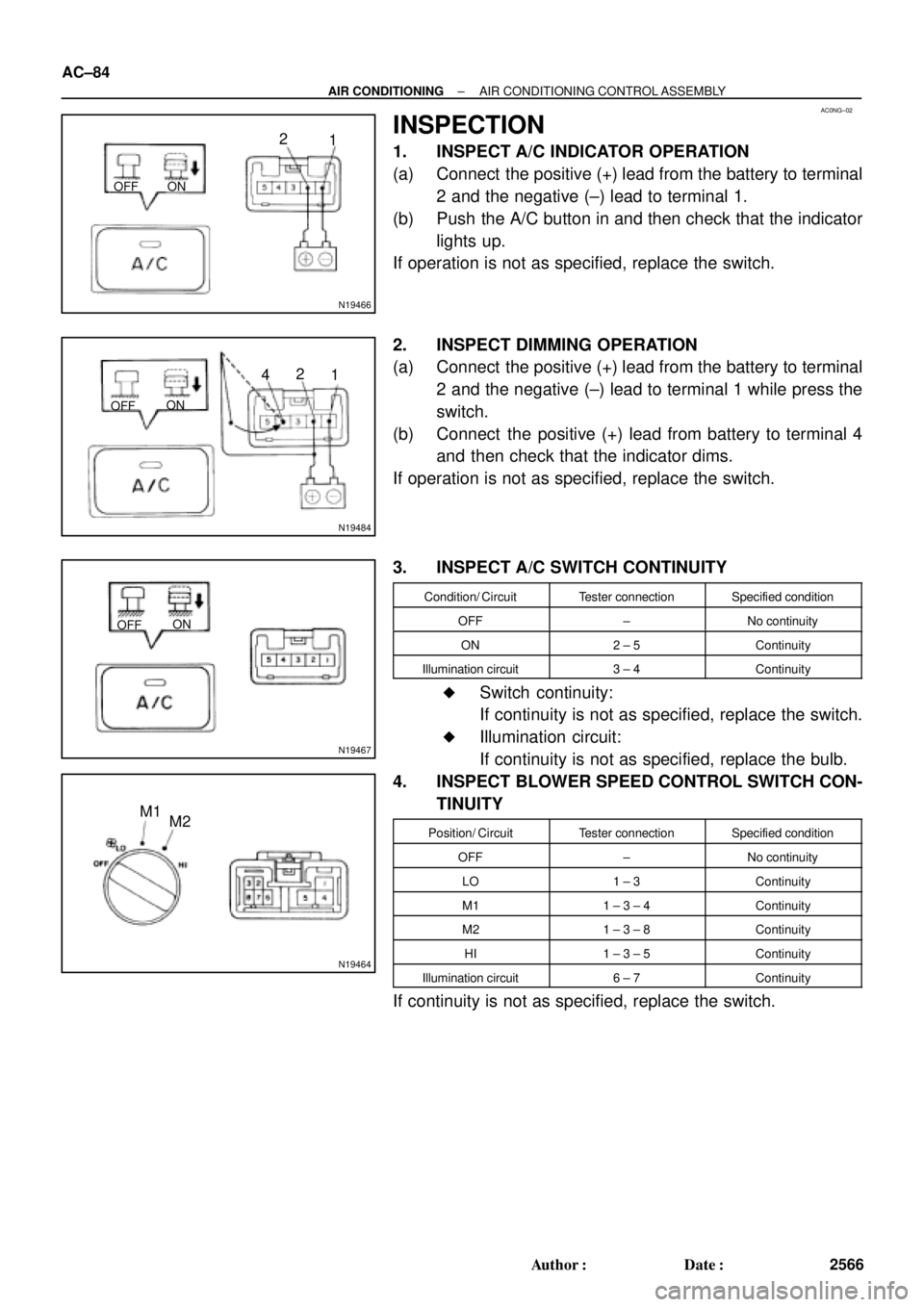
1. INSPECT A/C INDICATOR OPERATION
(a) Connect the positive (+) lead from the battery to terminal
2 and the negative (±) lead to terminal 1.
(b) Push the A/C button in and then check that the indicator
lights up.
If operation is not as specified, replace the switch.
2. INSPECT DIMMING OPERATION
(a) Connect the positive (+) lead from the battery to terminal
2 and the negative (±) lead to terminal 1 while press the
switch.
(b) Connect the positive (+) lead from battery to terminal 4
and then check that the indicator dims.
If operation is not as specified, replace the switch.
3. INSPECT A/C SWITCH CONTINUITY
Condition/ CircuitTester connectionSpecified condition
OFF±No continuity
ON2 ± 5Continuity
Illumination circuit3 ± 4Continuity
�Switch continuity:
If continuity is not as specified, replace the switch.
�Illumination circuit:
If continuity is not as specified, replace the bulb.
4. INSPECT BLOWER SPEED CONTROL SWITCH CON-
TINUITY
Position/ CircuitTester connectionSpecified condition
OFF±No continuity
LO1 ± 3Continuity
M11 ± 3 ± 4Continuity
M21 ± 3 ± 8Continuity
HI1 ± 3 ± 5Continuity
Illumination circuit6 ± 7Continuity
If continuity is not as specified, replace the switch.
Page 103 of 4592

AX039±01
Q10052
Q10339
0.8 ± 1.5 mm(0.031 ± 0.059 in.)200 mm
(7.87 in.)
± AUTOMATIC TRANSAXLE (A140E)THROTTLE CABLE
AX±9
1902 Author�: Date�:
THROTTLE CABLE
ON±VEHICLE REPAIR
1. DISCONNECT THROTTLE CABLE
(a) Disconnect the cable from the throttle linkage.
(b) Disconnect the cable from the cable clamps in the engine
compartment.
2. REMOVE PARK/NEUTRAL POSITION SWITCH
(See page AX±4)
3. REMOVE VALVE BODY (See page AX±5)
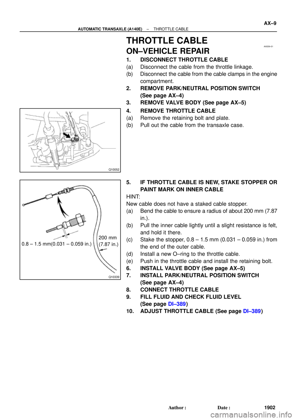
4. REMOVE THROTTLE CABLE
(a) Remove the retaining bolt and plate.
(b) Pull out the cable from the transaxle case.
5. IF THROTTLE CABLE IS NEW, STAKE STOPPER OR
PAINT MARK ON INNER CABLE
HINT:
New cable does not have a staked cable stopper.
(a) Bend the cable to ensure a radius of about 200 mm (7.87
in.).
(b) Pull the inner cable lightly until a slight resistance is felt,
and hold it there.
(c) Stake the stopper, 0.8 ± 1.5 mm (0.031 ± 0.059 in.) from
the end of the outer cable.
(d) Install a new O±ring to the throttle cable.
(e) Push in the throttle cable and install the retaining bolt.
6. INSTALL VALVE BODY (See page AX±5)
7. INSTALL PARK/NEUTRAL POSITION SWITCH
(See page AX±4)
8. CONNECT THROTTLE CABLE
9. FILL FLUID AND CHECK FLUID LEVEL
(See page DI±389)
10. ADJUST THROTTLE CABLE (See page DI±389)
Page 106 of 4592
AX03C±01
D00760
Shift Lock Override Cover
Shift Lock Override Button
Stop Light Switch
Key Interlock Solenoid
Shift Lock
Control Unit Assembly AX±12
± AUTOMATIC TRANSAXLE (A140E)SHIFT LOCK SYSTEM (TMC Made)
1905 Author�: Date�:
SHIFT LOCK SYSTEM (TMC Made)
LOCATION
Page 108 of 4592
AX03E±01
D00759
Shift Lock Override Cover
Shift Lock Override Button
Shift Lock Solenoid
Shift Lock Control Switch
Shift Lock Control ECU Key Interlock SolenoidStop Light Switch AX±14
± AUTOMATIC TRANSAXLE (A140E)SHIFT LOCK SYSTEM (TMMK Made)
1907 Author�: Date�:
SHIFT LOCK SYSTEM (TMMK Made)
LOCATION
Page 134 of 4592

Q09982
AX03R±01
Q00225
Q00270
Q00270
Q057310.8 ± 1.5 mm (0.031±0.059 in.)200 mm
(7.87 in.)
± AUTOMATIC TRANSAXLE (A541E)THROTTLE CABLE
AX±13
1933 Author�: Date�:
THROTTLE CABLE
ON±VEHICLE REPAIR
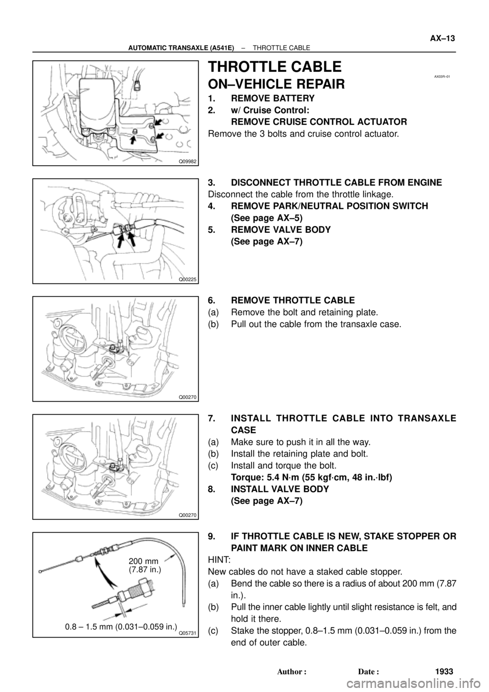
1. REMOVE BATTERY
2. w/ Cruise Control:
REMOVE CRUISE CONTROL ACTUATOR
Remove the 3 bolts and cruise control actuator.
3. DISCONNECT THROTTLE CABLE FROM ENGINE
Disconnect the cable from the throttle linkage.
4. REMOVE PARK/NEUTRAL POSITION SWITCH
(See page AX±5)
5. REMOVE VALVE BODY
(See page AX±7)
6. REMOVE THROTTLE CABLE
(a) Remove the bolt and retaining plate.
(b) Pull out the cable from the transaxle case.
7. INSTALL THROTTLE CABLE INTO TRANSAXLE
CASE
(a) Make sure to push it in all the way.
(b) Install the retaining plate and bolt.
(c) Install and torque the bolt.
Torque: 5.4 N´m (55 kgf´cm, 48 in.´lbf)
8. INSTALL VALVE BODY
(See page AX±7)
9. IF THROTTLE CABLE IS NEW, STAKE STOPPER OR
PAINT MARK ON INNER CABLE
HINT:
New cables do not have a staked cable stopper.
(a) Bend the cable so there is a radius of about 200 mm (7.87
in.).
(b) Pull the inner cable lightly until slight resistance is felt, and
hold it there.
(c) Stake the stopper, 0.8±1.5 mm (0.031±0.059 in.) from the
end of outer cable.