Page 39 of 4592

AC0M4±02
N01143
W
N01150
± AIR CONDITIONINGCOMPRESSOR AND MAGNETIC CLUTCH
AC±39
2521 Author�: Date�:
COMPRESSOR AND MAGNETIC
CLUTCH
ON±VEHICLE INSPECTION
1. INSPECT COMPRESSOR FOR METALLIC SOUND
(a) Start engine.
(b) Check if there is a metallic sound from the compressor
when the A/C switch is on.
If metallic sound is heard, replace the compressor assembly.
2. INSPECT REFRIGERANT PRESSURE
See ºON±VEHICLE INSPECTIONº of AIR CONDITIONING
SYSTEM on page AC±3.
3. INSPECT COMPRESSOR LOCK SENSOR RESIS-
TANCE
(a) Disconnect the connector.
(b) Measure resistance between terminals 1 and 2.
Standard resistance: 65 ± 125 W at 20 °C (68 °F)
If resistance is not as specified, replace the compressor assem-
bly.
4. INSPECT VISUALLY FOR LEAKAGE OF REFRIGER-
ANT FROM SAFETY SEAL
Using a gas leak detector, check for leakage of refrigerant.
If there is any leakage, replace the compressor assembly.
5. CHECK FOR LEAKAGE OF GREASE FROM CLUTCH
BEARING
6. CHECK FOR SIGNS OF OIL ON PRESSURE PLATE OR
ROTOR
7. INSPECT MAGNETIC CLUTCH BEARING FOR NOISE
(a) Start engine.
(b) Check for abnormal noise from near the compressor
when the A/C switch is OFF.
If abnormal noise is being emitted, replace the magnetic clutch.
8. INSPECT MAGNETIC CLUTCH OPERATION
(a) Disconnect the connector.
(b) Connect the positive (+) lead from the battery to terminal
4 and the negative (±) lead to the body ground.
(c) Check that the magnetic clutch is energized.
If operation is not as specified, replace the magnetic clutch.
Page 40 of 4592

AC0M4±02
N01143
W
N01150
± AIR CONDITIONINGCOMPRESSOR AND MAGNETIC CLUTCH
AC±39
2521 Author�: Date�:
COMPRESSOR AND MAGNETIC
CLUTCH
ON±VEHICLE INSPECTION
1. INSPECT COMPRESSOR FOR METALLIC SOUND
(a) Start engine.
(b) Check if there is a metallic sound from the compressor
when the A/C switch is on.
If metallic sound is heard, replace the compressor assembly.
2. INSPECT REFRIGERANT PRESSURE
See ºON±VEHICLE INSPECTIONº of AIR CONDITIONING
SYSTEM on page AC±3.
3. INSPECT COMPRESSOR LOCK SENSOR RESIS-
TANCE
(a) Disconnect the connector.
(b) Measure resistance between terminals 1 and 2.
Standard resistance: 65 ± 125 W at 20 °C (68 °F)
If resistance is not as specified, replace the compressor assem-
bly.
4. INSPECT VISUALLY FOR LEAKAGE OF REFRIGER-
ANT FROM SAFETY SEAL
Using a gas leak detector, check for leakage of refrigerant.
If there is any leakage, replace the compressor assembly.
5. CHECK FOR LEAKAGE OF GREASE FROM CLUTCH
BEARING
6. CHECK FOR SIGNS OF OIL ON PRESSURE PLATE OR
ROTOR
7. INSPECT MAGNETIC CLUTCH BEARING FOR NOISE
(a) Start engine.
(b) Check for abnormal noise from near the compressor
when the A/C switch is OFF.
If abnormal noise is being emitted, replace the magnetic clutch.
8. INSPECT MAGNETIC CLUTCH OPERATION
(a) Disconnect the connector.
(b) Connect the positive (+) lead from the battery to terminal
4 and the negative (±) lead to the body ground.
(c) Check that the magnetic clutch is energized.
If operation is not as specified, replace the magnetic clutch.
Page 42 of 4592
AC0M6±02
N20277
P19978
± AIR CONDITIONINGCOMPRESSOR AND MAGNETIC CLUTCH
AC±41
2523 Author�: Date�:
REMOVAL
1. RUN ENGINE AT IDLE SPEED WITH A/C ON FOR
APPROX.10 MINUTES
2. STOP ENGINE
3. DISCONNECT NEGATIVE (±) TERMINAL CABLE
FROM BATTERY
4. DISCHARGE REFRIGERANT FROM REFRIGERATION
SYSTEM
5. REMOVE DRIVE BELT
(See page AC±17)
6. 1MZ±FE engine models:
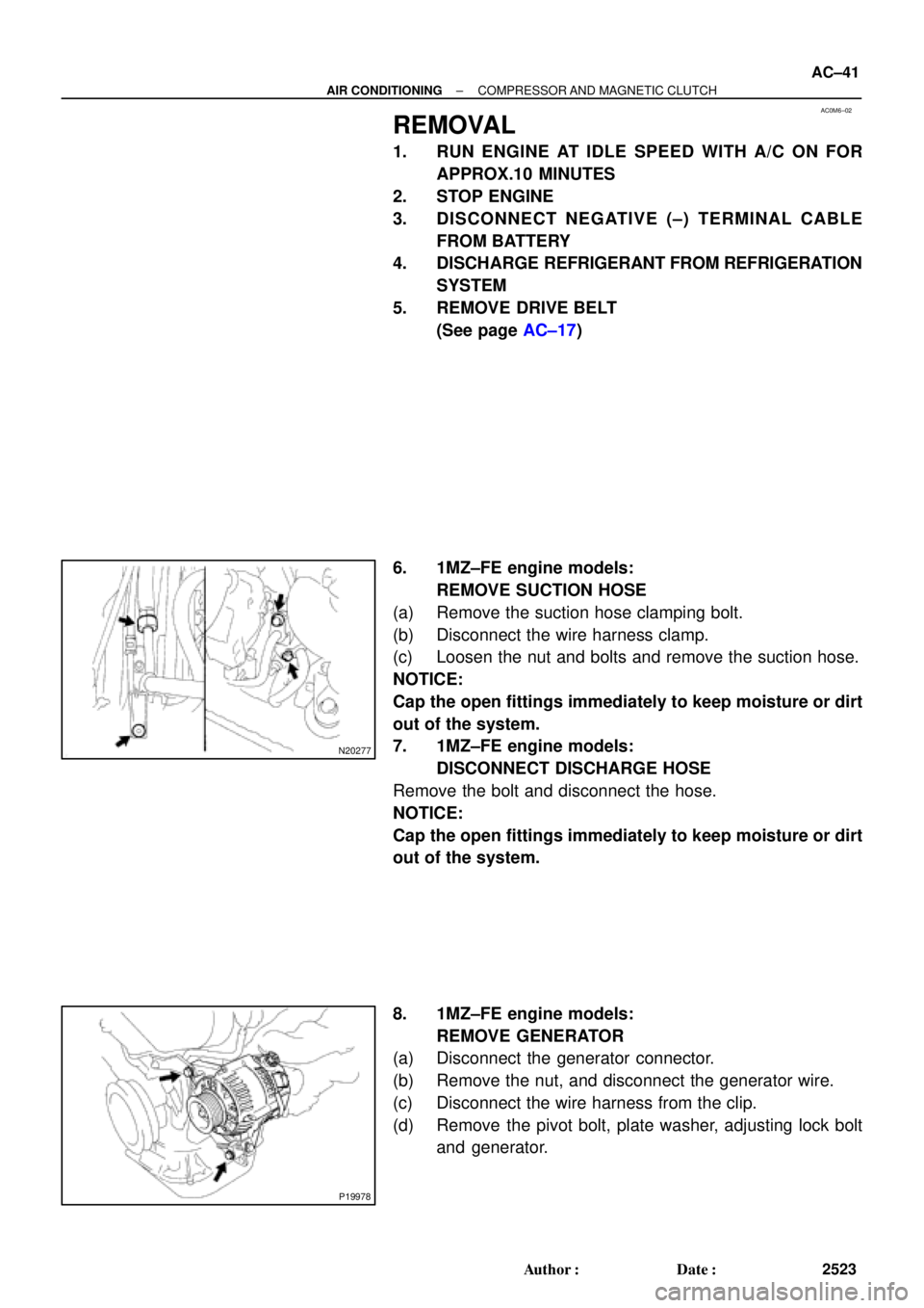
REMOVE SUCTION HOSE
(a) Remove the suction hose clamping bolt.
(b) Disconnect the wire harness clamp.
(c) Loosen the nut and bolts and remove the suction hose.
NOTICE:
Cap the open fittings immediately to keep moisture or dirt
out of the system.
7. 1MZ±FE engine models:
DISCONNECT DISCHARGE HOSE
Remove the bolt and disconnect the hose.
NOTICE:
Cap the open fittings immediately to keep moisture or dirt
out of the system.
8. 1MZ±FE engine models:
REMOVE GENERATOR
(a) Disconnect the generator connector.
(b) Remove the nut, and disconnect the generator wire.
(c) Disconnect the wire harness from the clip.
(d) Remove the pivot bolt, plate washer, adjusting lock bolt
and generator.
Page 47 of 4592
AC0M8±02
N04963
Dial Indicator AC±46
± AIR CONDITIONINGCOMPRESSOR AND MAGNETIC CLUTCH
2528 Author�: Date�:
REASSEMBLY
Reassembly is in the reverse order of disassembly
(See page AC±43).
AFTER REASSEMBLY, CHECK MAGNETIC CLUTCH
CLEARANCE
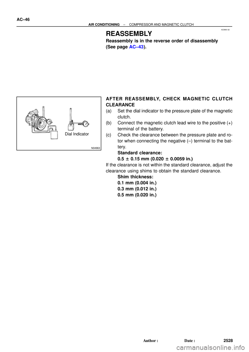
(a) Set the dial indicator to the pressure plate of the magnetic
clutch.
(b) Connect the magnetic clutch lead wire to the positive (+)
terminal of the battery.
(c) Check the clearance between the pressure plate and ro-
tor when connecting the negative (±) terminal to the bat-
tery.
Standard clearance:
0.5 ± 0.15 mm (0.020 ± 0.0059 in.)
If the clearance is not within the standard clearance, adjust the
clearance using shims to obtain the standard clearance.
Shim thickness:
0.1 mm (0.004 in.)
0.3 mm (0.012 in.)
0.5 mm (0.020 in.)
Page 64 of 4592
AC221±01
N20295
N16762
21
N20295
± AIR CONDITIONINGBLOWER MOTOR
AC±63
2545 Author�: Date�:
BLOWER MOTOR
INSPECTION
1. REMOVE GLOVE COMPARTMENT
(See page BO±75)
2. REMOVE BLOWER MOTOR
(a) Disconnect the connector.
(b) Remove the 3 screws and blower motor.
3. INSPECT BLOWER MOTOR OPERATION
Connect the positive (+) lead from the battery to terminal 2 and
the negative (±) lead to terminal 1, then check that the motor op-
erations smoothly.
If operation is not as specified, replace the blower motor.
4. INSTALL BLOWER MOTOR
(a) Install the blower motor with the 3 screws.
(b) Connect the connector.
5. INSTALL GLOVE COMPARTMENT
(See page BO±81)
Page 66 of 4592
AC223±01
N20287
N20278
Z19151
DEF.FOOT/DEF.
FOOT BI±LEVEL
FACE
1
2
3
4 5 6
736°
0 ± 2.5° 36° 40°53°
± AIR CONDITIONINGAIR OUTLET SERVOMOTOR
AC±65
2547 Author�: Date�:
AIR OUTLET SERVOMOTOR
INSPECTION
1. REMOVE NO. 1 LOWER INSTRUMENT PANEL
2. REMOVE LH INSTRUMENT LOWER PANEL
(See page BO±75)
3. REMOVE SERVOMOTOR
(a) Release the claw and pull out the plate.
(b) Disconnect the connector.
(c) Remove the 3 screws and servomotor.
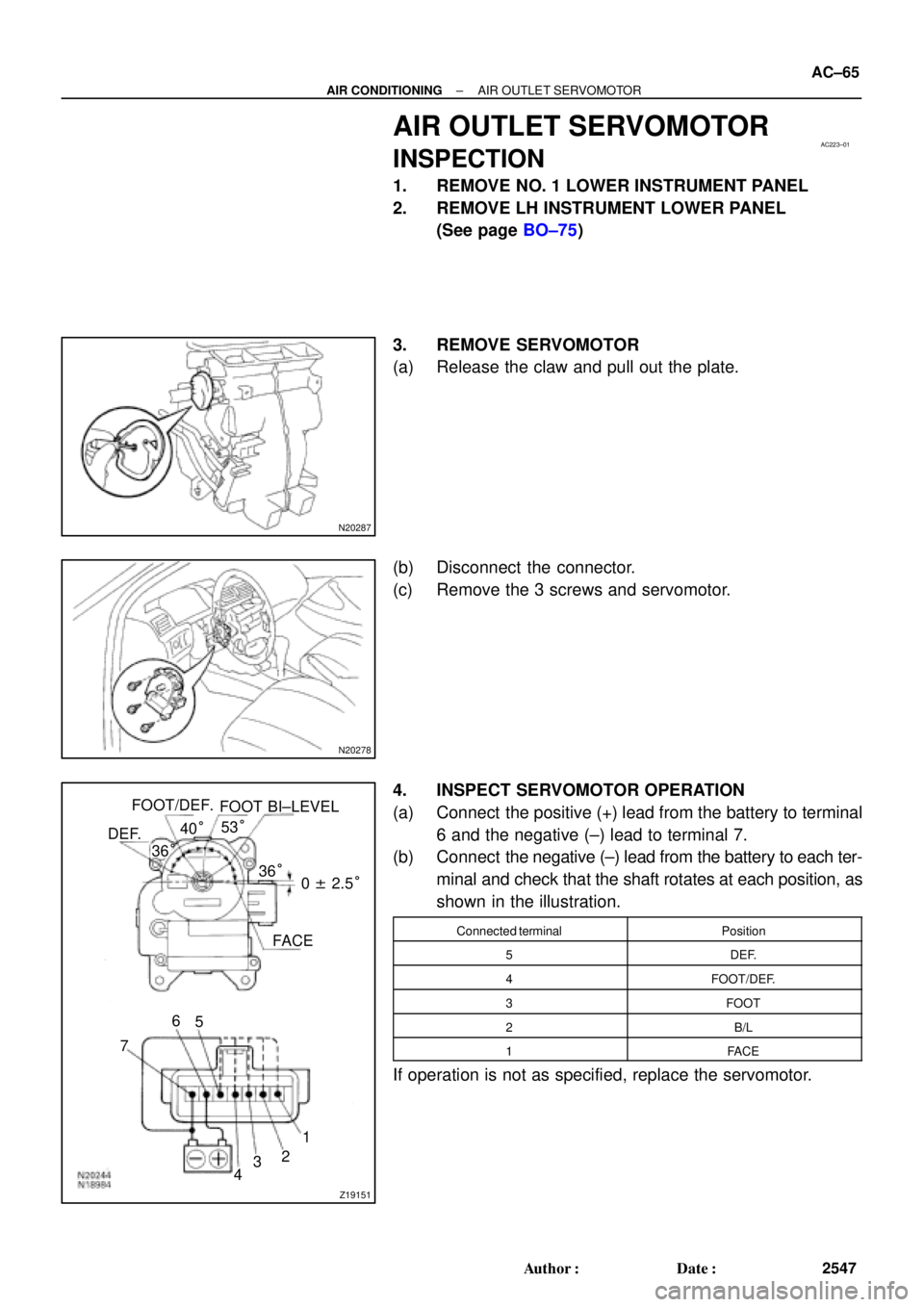
4. INSPECT SERVOMOTOR OPERATION
(a) Connect the positive (+) lead from the battery to terminal
6 and the negative (±) lead to terminal 7.
(b) Connect the negative (±) lead from the battery to each ter-
minal and check that the shaft rotates at each position, as
shown in the illustration.
Connected terminalPosition
5DEF.
4FOOT/DEF.
3FOOT
2B/L
1FACE
If operation is not as specified, replace the servomotor.
Page 75 of 4592
AC0N6±02
N20290
21
A AC±74
± AIR CONDITIONINGCONDENSER FAN
2556 Author�: Date�:
CONDENSER FAN
ON±VEHICLE INSPECTION
1. INSPECT CONDENSER FAN OPERATION
Inspect the fan operation, as shown in the chart below.
Test conditions:
�Ignition switch ON
�Blower speed control switch position ºHIº
�A/C switch ON
ConditionFan operation (Fan speed)
Engine coolant temperature
83°C (181°F) or belowNot rotate
Engine coolant temperature
98°C (208°F) or aboveRotate
Refrigerant pressure is less than
1,520 kPa (15.5 kgf/cm2, 220 psi)Not rotate (Low Speed)
Refrigerant pressure is 1,520 kPa
(15.5 kgf/cm2, 220 psi) or aboveRotate (High Speed)
If operation is not as specified, proceed next inspection.
2. INSPECT CONDENSER FAN MOTOR OPERATION
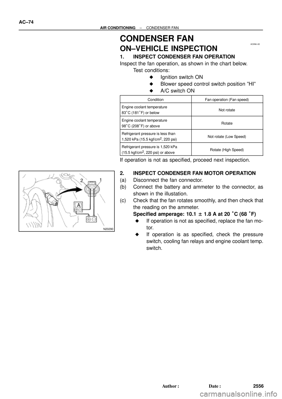
(a) Disconnect the fan connector.
(b) Connect the battery and ammeter to the connector, as
shown in the illustation.
(c) Check that the fan rotates smoothly, and then check that
the reading on the ammeter.
Specified amperage: 10.1 ± 1.8 A at 20 °C (68 °F)
�If operation is not as specified, replace the fan mo-
tor.
�If operation is as specified, check the pressure
switch, cooling fan relays and engine coolant temp.
switch.
Page 85 of 4592
AC0NG±02
N19466
ON OFF
2
1
N19484
ON
OFF
2
1 4
N19467
ON
OFF
N19464
M1
M2 AC±84
± AIR CONDITIONINGAIR CONDITIONING CONTROL ASSEMBLY
2566 Author�: Date�:
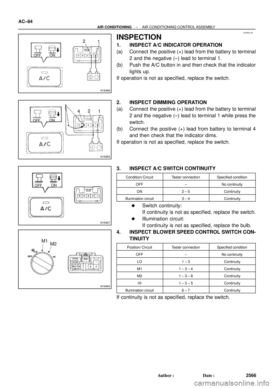
INSPECTION
1. INSPECT A/C INDICATOR OPERATION
(a) Connect the positive (+) lead from the battery to terminal
2 and the negative (±) lead to terminal 1.
(b) Push the A/C button in and then check that the indicator
lights up.
If operation is not as specified, replace the switch.
2. INSPECT DIMMING OPERATION
(a) Connect the positive (+) lead from the battery to terminal
2 and the negative (±) lead to terminal 1 while press the
switch.
(b) Connect the positive (+) lead from battery to terminal 4
and then check that the indicator dims.
If operation is not as specified, replace the switch.
3. INSPECT A/C SWITCH CONTINUITY
Condition/ CircuitTester connectionSpecified condition
OFF±No continuity
ON2 ± 5Continuity
Illumination circuit3 ± 4Continuity
�Switch continuity:
If continuity is not as specified, replace the switch.
�Illumination circuit:
If continuity is not as specified, replace the bulb.
4. INSPECT BLOWER SPEED CONTROL SWITCH CON-
TINUITY
Position/ CircuitTester connectionSpecified condition
OFF±No continuity
LO1 ± 3Continuity
M11 ± 3 ± 4Continuity
M21 ± 3 ± 8Continuity
HI1 ± 3 ± 5Continuity
Illumination circuit6 ± 7Continuity
If continuity is not as specified, replace the switch.