Page 1227 of 4592

± DIAGNOSTICSENGINE (5S±FE)
DI±15
250 Author�: Date�:
(b) TOYOTA Enhanced Signals.
TOYOTA hand±held tester displayMeasurement ItemNormal Condition*1
MISFIRE RPMEngine RPM for first misfire rangeMisfire 0: 0 rpm
MISFIRE LOADEngine load for first misfire rangeMisfire 0: 0 g/r
INJECTORFuel injection time for cylinder No.1Idling: 2.9 ~ 5.1 ms
IAC DUTY RATIOIntake Air Control Valve Duty Ratio
Opening ratio rotary solenoid type IAC valveIdling: 25 ~ 62 %
STARTER SIGStarter SignalCranking: ON
CTP SIGClosed Throttle Position SignalThrottle fully closed: ON
A/C SIGA/C Switch SignalA/C ON: ON
PNP SIGPark/Neutral Position Switch SignalP or N position: ON
ELECTCL LOAD SIGElectrical Load SignalDefogger S/W ON: ON
STOP LIGHT SWStop Light Switch SignalStop light switch ON: ON
PS OIL PRESS SWPower Steering Oil Pressure Switch SignalTurn steering wheel: ON
FC IDLFuel Cut Idle: Fuel cut when throttle valve fully
closed, during decelerationFuel cut operating: ON
FC TAUFuel Cut TAU: Fuel cut during very light loadFuel cut operating: ON
CYL#1, CYL#2, CYL#3, CYL#4Abnormal revolution variation for each cylinder0 %
IGNITIONTotal number of ignition for every 1,000 revolu-
tions0 ~ 2,000 rpm
EGR SYSTEMEGR system operating conditionIdling: OFF
FUEL PUMPFuel Pump SignalIdling: ON
A/C CUT SIGA/C Cut SignalA/C S/W OFF: ON
A/C MAG CLUTCHA/C Switch SignalA/C ON: ON
EVAP (PURGE) VSVEVAP VSV SignalVSV operating: Avove 30 %
VAPOR PRESS VSVVapor Pressure VSV SignalVSV operating: ON
TOTAL FT B1Total Fuel Trim Bank 1: Average value for fuel
trim system of bank 1Idling: 0.8 ~ 1.2 V
O2 LR B1, S1 *2
Heated Oxygen Sensor Lean Rich Bank 1 Sen-
sor 1: Response time for oxygen sensor output to
switch from lean to rich
Idling after warming up: 0 ~ 1,000 msec.
O2 RL B1, S1 *2
Heated Oxygen Sensor Rich Lean Bank 1 Sen-
sor 1: Response time for oxygen sensor output to
switch from rich to lean
Idling after warming up: 0 ~ 1,000 msec.
*1: If no conditions are specifically stated for ºldlingº, it means the shift lever is at N or P position, the A/C
switch is OFF and all accessory switches are OFF.
*2: Except California Specification vehicles.
Page 1388 of 4592
A03606
ECM
STA 11
E1 E7 Instrument
Panel J/BPark/Neutral
Position Switch
Clutch Start
SwitchB
J7
J7
B J8CJ/C II2 10 11
II26
2
B±O
5
1 B±W (M/T)
GR B±W (A/T)
B±WB±O (A/T,*2)
GR (A/T,*1) B±W
J/C J29
B B
B 3
1J 4
1K
5
1B 1K5
STARTER
R
8
7
W±R
IG SwitchW±R
Engine Room
J/B No. 2B
B FL
Block
B±G
B±R
BatteryStarter 11
W±B
A
J11
J/C
IG
42L
1
2A
3
2B
AM2
MAINST
Relay11 2 J
92K 52D 1 1
F6 F41 5
2 3
B±O (*2)
S2B±R MAIN
FL
GR (*1)(A/T)
S1
*1: TMC Made
*2: TMMK Made
GR (*1)
(*2)
(M/T)
B±O (*2) GR (*1)
DI±176
± DIAGNOSTICSENGINE (5S±FE)
411 Author�: Date�:
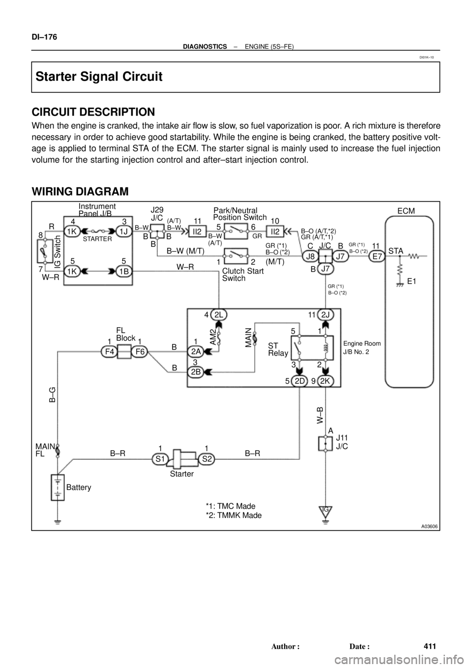
Starter Signal Circuit
CIRCUIT DESCRIPTION
When the engine is cranked, the intake air flow is slow, so fuel vaporization is poor. A rich mixture is therefore
necessary in order to achieve good startability. While the engine is being cranked, the battery positive volt-
age is applied to terminal STA of the ECM. The starter signal is mainly used to increase the fuel injection
volume for the starting injection control and after±start injection control.
WIRING DIAGRAM
DI01K±10
Page 1395 of 4592
A00325
BatteryMAIN IG Switch
AM2EFI
MAIN
FLStarter ST RelayPark/Neutral Position Switch
(Clutch Start Switch)EFI RelayCIR OPN Relay
Fuel Pump
ECM
FC
Tr
STA
NE (STA Signal)
(NE Signal) IGN
STARTER ST
± DIAGNOSTICSENGINE (5S±FE)
DI±183
418 Author�: Date�:
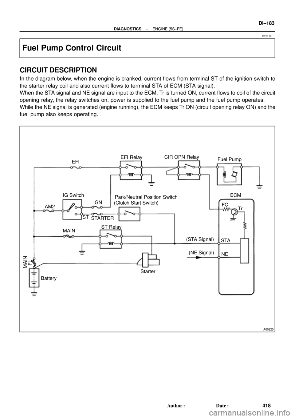
Fuel Pump Control Circuit
CIRCUIT DESCRIPTION
In the diagram below, when the engine is cranked, current flows from terminal ST of the ignition switch to
the starter relay coil and also current flows to terminal STA of ECM (STA signal).
When the STA signal and NE signal are input to the ECM, Tr is turned ON, current flows to coil of the circuit
opening relay, the relay switches on, power is supplied to the fuel pump and the fuel pump operates.
While the NE signal is generated (engine running), the ECM keeps Tr ON (circuit opening relay ON) and the
fuel pump also keeps operating.
DI01M±05
Page 1396 of 4592
A07555
Battery
EFI
AM2
123
3 1J
B2A
2J Instrument Panel J/B
B
1B 1W
37
1 5
IG Switch
1
B±W
B±RST RelayEFI Relay
5
6
2 3
1 11 410
4
5 4
5
A 2B STARTER
(M/T)
B±G
II23
B±W
II211
Starter
Park/Neutral
Position Switch
Clutch Start
Switch
5 7
B±R Engine Room J/B No.2
2C
2F IGN
FL Block1
2D1
BMAIN
B±O (*3) W±B
GR (*2)
10B
C
1
CIR
OPN
Relay
L±B
IGG±R
W±B
14 2L
E7FCECM
E01
1
S1S2
Engine Room R/B
No.1
2
J40
J/C
G±RL±B
5 93
Fuel
Pump
L±B
R
EB B±R
GR
W±R
B±W
B±WB±O (*3)(A/T)
BL
J/CB±R
J8
2K
J7
B
1 1 1
B 1K
1K
1K
8 7
6
EB1 4
J29
J/C J11
J/CF6 1 W±R
MAIN
FL4
5 2K
2
B±R (*4)
*1: w/ Immobiliser(*1)
MREL
E107 B±W
B
B
B±WII4
6
F41
GR (*2)
*2: TMC Made
*3: TMMK Made A
(*1)
(*1)
GR (*2)
B±O (*3)(M/T)
*4: w/o Immobiliser
EB1 B±R
B±R (*1)
B±R (*4)
IK17
55
7
ID1
7 W±B
W±B
DI±184
± DIAGNOSTICSENGINE (5S±FE)
419 Author�: Date�:
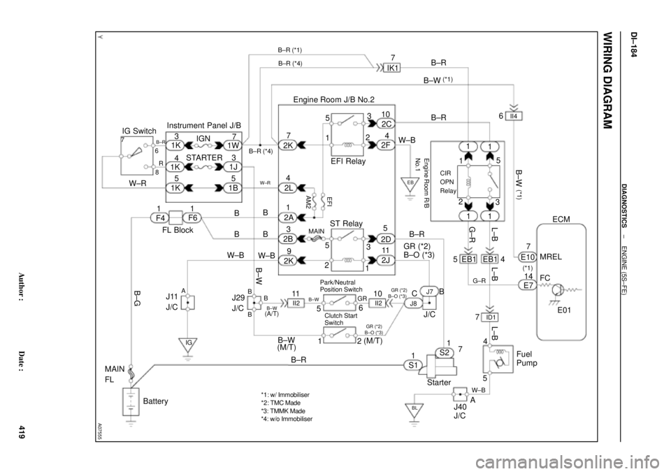
WIRING DIAGRAM
Page 1587 of 4592
A07451
ECM
E01 FC 3
E7
G±R
5EB1
G±R 1
1
1 1 15
3
2
CIR OPN Relay
Engine Room R/B
L±B
EB1
ID1L±B
A
A
5 4 10
7
W±B
W±BJ11
Junction
Connector
IG BL
StarterS2
B±R
EB
B±R 2D
2K 2F
9 5 4 2C 10
II2
10
Junction
Connector
J8 J7
C B(A/T)
(A/T) GR
(M/T) B±WPark/
Nutral
Position
Switch
6 5(A/T)
B±W(A/T)
B±WII2
11 11
ST Relay
B B
B EFI Relay23
15
2
13 5
2J 2K
W±BB±R W±B B±RB±W
7 8R1K
W±R
1J
43
1B
STARTER
5 5
1
2 B±W
W±B
2A
2B31
2L 4 AM27Instrument Panel J/B
Battery
B±GFL
MAIN F6
F4 1
Fusible
Link
BlockB B
EFI
MAINB+
MREL
8
E7
B±R
Fuel
Pump
1W 1K1
IGN
1
ST2
IG2
AM2Clutch
Start
Switch
L±BW±B
Junction
Connector
A
J40
Junction
Connector
1K 7
*B±O *1GR
(M/T)
*B±O *1GR
J35 J35C
*B±O *1GR
B±W
B±R
Junction
Connector J26
1
7
3
1K
*: TMMK made
*
1: TMC made
± DIAGNOSTICSENGINE (1MZ±FE)
DI±375
610 Author�: Date�:
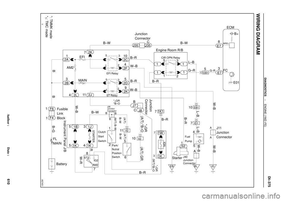
WIRING DIAGRAM
Page 1596 of 4592
A07453
5
1B±R
1ECM Engine Room J/B
E77
STA
E1 S2
Starter W±B 9 5
2D
2K 3
2
Sarter Relay MAIN
2B3
2J 11 B
J7
J7 J8
Junction
Connector CB
B II210 From Battery
W±B
W±B
A
A J11
Junction
Connector
IG Instrument
Panel J/B
STARTER
From Ignition Switch11
II2
B±W(A/T)
B±W(A/T)
B±W
Park/Neutral
Position Switch 6
5
B±W(A/T)
B
B
B
1J
1K 3
4
B±W(M/T)
12
Clutch Start Switch
GR
*1GR1
*1B±O
*GR
*GR
*GR
*B±O(M/T)
J16
Junction
Connector
*B±O
*: TMMK made
*
1: TMC made
*1B±O
DI±384
± DIAGNOSTICSENGINE (1MZ±FE)
619 Author�: Date�:
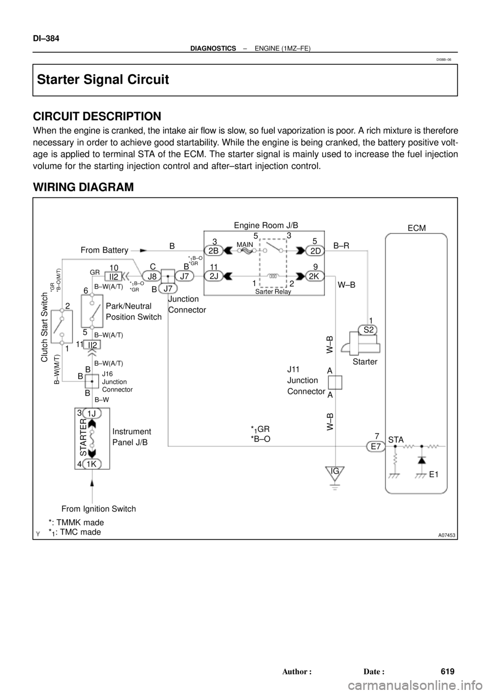
Starter Signal Circuit
CIRCUIT DESCRIPTION
When the engine is cranked, the intake air flow is slow, so fuel vaporization is poor. A rich mixture is therefore
necessary in order to achieve good startability. While the engine is being cranked, the battery positive volt-
age is applied to terminal STA of the ECM. The starter signal is mainly used to increase the fuel injection
volume for the starting injection control and after±start injection control.
WIRING DIAGRAM
DI08B±06
Page 2119 of 4592

Input Signal
Indicator Light
Blinking Pattern
Clutch switch
OFF (Depress
clutch pedal)
LightON
OFFSW ON
SW OFF
± DIAGNOSTICSCRUISE CONTROL SYSTEM
DI±907
1142 Author�: Date�:
Clutch Switch Circuit
CIRCUIT DESCRIPTION
When the clutch pedal is depressed, the clutch switch sends a signal to the cruise control ECU. When the
signal is input to the cruise control ECU during cruise control driving, the cruise control ECU cancels cruise
control.
WIRING DIAGRAM
Refer to PNP switch circuit on page DI±904.
INSPECTION PROCEDURE
1 Check starter operation.
CHECK:
Check that the starter operates normally and that the engine starts.
NG Proceed to engine troubleshooting
(5S±FE: See page ST±1)
(1MZ±FE: See page ST±1).
OK
2 Input signal check.
PREPARATION:
See input signal check on page DI±870.
CHECK:
Check the indicator lights when clutch pedal is depressed.
OK:
The indicator light goes off when shifting into clutch
pedal is depressed.
OK Proceed to next circuit inspection shown on
problem symptoms table (See page DI±879).
NG
DI08W±04
Page 2121 of 4592

Input Signal
Indicator Light
Blinking Pattern
Clutch switch
OFF (Depress
clutch pedal)
LightON
OFFSW ON
SW OFF
± DIAGNOSTICSCRUISE CONTROL SYSTEM
DI±907
1142 Author�: Date�:
Clutch Switch Circuit
CIRCUIT DESCRIPTION
When the clutch pedal is depressed, the clutch switch sends a signal to the cruise control ECU. When the
signal is input to the cruise control ECU during cruise control driving, the cruise control ECU cancels cruise
control.
WIRING DIAGRAM
Refer to PNP switch circuit on page DI±904.
INSPECTION PROCEDURE
1 Check starter operation.
CHECK:
Check that the starter operates normally and that the engine starts.
NG Proceed to engine troubleshooting
(5S±FE: See page ST±1)
(1MZ±FE: See page ST±1).
OK
2 Input signal check.
PREPARATION:
See input signal check on page DI±870.
CHECK:
Check the indicator lights when clutch pedal is depressed.
OK:
The indicator light goes off when shifting into clutch
pedal is depressed.
OK Proceed to next circuit inspection shown on
problem symptoms table (See page DI±879).
NG
DI08W±04