Page 107 of 4592

4 (KLS
+)
3 (E)
2 (STP)1 (ACC)
Wire Harness Side
Q09456
1 (KLS+)
2 (E)
Q09457
1 (KLS+)
2 (E)
± AUTOMATIC TRANSAXLE (A140E)SHIFT LOCK SYSTEM (TMC Made)
AX±13
1906 Author�: Dat")
AX03D±01
D00758
5 (IG)
4 (KLS
+)
3 (E)
2 (STP)1 (ACC)
Wire Harness Side
Q09456
1 (KLS+)
2 (E)
Q09457
1 (KLS+)
2 (E)
± AUTOMATIC TRANSAXLE (A140E)SHIFT LOCK SYSTEM (TMC Made)
AX±13
1906 Author�: Date�:
INSPECTION
1. INSPECT SHIFT LOCK CONTROL UNIT ASSEMBLY
Using a voltmeter, measure the voltage at each terminal.
HINT:
Do not disconnect the shift lock control unit assembly connec-
tor.
TerminalMeasuring ConditionVoltage (V)
1 ± 3 (ACC ± E)Ignition switch ACC10 ± 14
5 ± 3 (IG ± E)Ignition switch ON10 ± 14
2 ± 3 (STP ± E)Depressing brake pedal10 ± 14
4 ± 3 (KLS+ ± E)
(1) Ignition switch ACC and P position
(2) Ignition switch ACC and except P position
(3) Ignition switch ACC and except P position (After approx. 1 second)0
7.5 ± 11
6 ± 9.5
2. INSPECT KEY INTERLOCK SOLENOID
(a) Disconnect the solenoid connector.
(b) Using an ohmmeter, measure resistance between termi-
nals.
Standard resistance: 12.5 ± 16.5 W
If resistance value is not as specified, replace the solenoid.
(c) Apply battery positive voltage between terminals. Check
that an operation noise can be heard from the solenoid.
If the solenoid does not operate, replace the solenoid.
Page 110 of 4592
Q09456
2 (E)1 (KLS
+)
Q09457
2 (E)1 (KLS
+)
Q09464
3 (P1)
4 (P2) 1 (P) AX±16
± AUTOMATIC TRANSAXLE (A140E)SHIFT LOCK SYSTEM (TMMK Made)
1909 Author�: Date�:
3. INSPECT KEY INTERLOCK SOLENOID
(a) Disconnect the solenoid connector.
(b) Using an ohmmeter, measure resistance between termi-
nals.
Standard resistance: 12.5 ± 16.5 W
If resistance value is not as specified, replace the solenoid.
(c) Apply battery positive voltage between terminals. Check
that an operation noise can be heard from the solenoid.
If the solenoid does not operate, replace the solenoid.
4. INSPECT SHIFT LOCK CONTROL SWITCH
Inspect that there is continuity between each terminal.
Shift positionTester connectionSpecified value
P position (Release
button is not pushed)1 ± 3 (P ± P1)Continuity
P position (Release
button is pushed)1 ± 3 (P ± P1)
1 ± 4 (P ± P2)Continuity
R, N, D, 2, L position1 ± 4 (P ± P2)Continuity
If continuity is not as specified, replace the switch.
Page 138 of 4592
 5 (IG)
4 (KLS+)
3 (E)
2 (STP)
Wire Harness Side
Q09456
1 (KLS+)
2 (E)
Q09457
1 (KLS+)
2 (E)
(±) (+)
± AUTOMATIC TRANSAXLE (A541E)SHIFT LOCK SYSTEM (TMC Made)
AX±17
1937 Aut")
AX03U±02
Q09455
1 (ACC) 5 (IG)
4 (KLS+)
3 (E)
2 (STP)
Wire Harness Side
Q09456
1 (KLS+)
2 (E)
Q09457
1 (KLS+)
2 (E)
(±) (+)
± AUTOMATIC TRANSAXLE (A541E)SHIFT LOCK SYSTEM (TMC Made)
AX±17
1937 Author�: Date�:
INSPECTION
1. INSPECT SHIFT LOCK CONTROL UNIT ASSEMBLY
Using a voltmeter, measure the voltage at each terminal.
HINT:
Do not disconnect the shift lock control unit assembly connec-
tor.
TerminalMeasuring ConditionVoltage (V)
1 ± 3 (ACC ± E)Ignition switch ACC10 ± 14
5 ± 3 (IG ± E)Ignition switch ON10 ± 14
2 ± 3 (STP ± E)Depressing brake pedal10 ± 14
4 ± 3 (KLS+ ± E)
(1) Ignition switch ACC and P position
(2) Ignition switch ACC and except P position
(3) Ignition switch ACC and except P position (After approx. 1 second)0
7.5 ± 11
6 ± 9.5
2. INSPECT KEY INTERLOCK SOLENOID
(a) Disconnect the solenoid connector.
(b) Using an ohmmeter, measure resistance between termi-
nals.
Standard resistance: 12.5 ± 16.5 W
If resistance value is not as specified, replace the solenoid.
(c) Apply battery positive voltage between terminals. Check
that an operation noise can be heard from the solenoid.
If the solenoid does not operated, replace the solenoid.
Page 141 of 4592
Q09456
1 (KLS+)
2 (E)
Q09457
1 (KLS+)
2 (E)
(±) (+)
Q09464
3 (P1) 4 (P2) 1 (P) AX±20
± AUTOMATIC TRANSAXLE (A541E)SHIFT LOCK SYSTEM (TMMK Made)
1940 Author�: Date�:
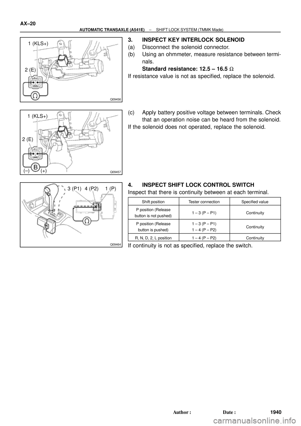
3. INSPECT KEY INTERLOCK SOLENOID
(a) Disconnect the solenoid connector.
(b) Using an ohmmeter, measure resistance between termi-
nals.
Standard resistance: 12.5 ± 16.5 W
If resistance value is not as specified, replace the solenoid.
(c) Apply battery positive voltage between terminals. Check
that an operation noise can be heard from the solenoid.
If the solenoid does not operated, replace the solenoid.
4. INSPECT SHIFT LOCK CONTROL SWITCH
Inspect that there is continuity between at each terminal.
Shift positionTester connectionSpecified value
P position (Release
button is not pushed)1 ± 3 (P ± P1)Continuity
P position (Release
button is pushed)1 ± 3 (P ± P1)
1 ± 4 (P ± P2)Continuity
R, N, D, 2, L position1 ± 4 (P ± P2)Continuity
If continuity is not as specified, replace the switch.
Page 595 of 4592

BE0A3±02
N14824
LOCKACC
ON
1 3 4
5 76 8
START2
N20125
OFF
ON
1
2
N20126
101
6
5
N20127
101
6
5 BE±14
± BODY ELECTRICALIGNITION SWITCH AND KEY UNLOCK WARNING
SWITCH
2234 Author�: Date�:
INSPECTION
1. INSPECT IGNITION SWITCH CONTINUITY
Switch positionTester connectionSpecified condition
LOCK±No continuity
ACC2 ± 3Continuity
ON2 ± 3 ± 4
6 ± 7Continuity
START1 ± 2 ± 4
6 ± 7 ± 8Continuity
If continuity is not as specified, replace the switch.
2. INSPECT KEY UNLOCK WARNING SWITCH CONTI-
NUITY
Switch positionTester connectionSpecified condition
OFF (Key removed)±No continuity
ON (Key set)1 ± 2Continuity
If continuity is not as specified, replace the switch.
3. Key unlock warning system:
INSPECT INTEGRATION RELAY (TYPE A) OPERA-
TION
(a) Connect the positive (+) lead from the battery to terminal
1.
(b) Connect the negative (±) lead from the battery to termi-
nals 5, 6 and 10.
(c) Check the buzzer sounds.
(d) Disconnect the negative (±) lead from the battery to termi-
nal 6.
(e) Check that the buzzerr stops sounding.
Page 596 of 4592
 Connect the negative (±) lea")
N20128
101
6
5
N20129
10
1 6
5
N20130
101 65
N20131
101 65
N20132
101 6
5
± BODY ELECTRICALIGNITION SWITCH AND KEY UNLOCK WARNING
SWITCHBE±15
2235 Author�: Date�:
(f) Connect the negative (±) lead from the battery to terminal
6.
(g) Disconnect the negative (±) lead from the battery to termi-
nal 5.
(h) Check that the buzzerr stops sounding.
If operation is not as specified, replace the relay.
4. Key unlock warning system:
INSPECT INTEGRATION RELAY (TYPE B) OPERA-
TION
(a) Connect the positive (+) lead from the battery to terminal
1.
(b) Connect the negative (±) lead from the battery to termi-
nals 5, 6 and 10.
(c) Check the buzzerr sounds.
(d) Disconnect the negative (±) lead from the battery to termi-
nal 6.
(e) Check that the buzzerr stops sounding.
(f) Connect the negative (±) lead from the battery to terminal
6.
(g) Disconnect the negative (±) lead from the battery to termi-
nal 5.
(h) Check that the buzzerr stops sounding.
If operation is not as specified, replace the relay.
5. Key unlock warning system:
INSPECT INTEGRATION RELAY (TYPE C) OPERA-
TION
(a) Connect the positive (+) lead from the battery to terminal
1.
(b) Connect the negative (±) lead from the battery to termi-
nals 5, 6 and 10.
(c) Check the buzzerr sounds.
Page 597 of 4592
 Disconnect the negat")
N20133
101 65
N20134
101 65
N20135
Junction block side:
1 2 3 4 5 6 7 8 10 11 9 12
BE±16± BODY ELECTRICALIGNITION SWITCH AND KEY UNLOCK WARNING
SWITCH
2236 Author�: Date�:
(d) Disconnect the negative (±) lead from the battery to termi-
nal 6.
(e) Check that the buzzerr stops sounding.
(f) Connect the negative (±) lead from the battery to terminal
6.
(g) Disconnect the negative (±) lead from the battery to termi-
nal 5.
(h) Check that the buzzerr stops sounding.
If operation is not as specified, replace the relay.
6. INSPECT INTEGRATION RELAY (TYPE A) CIRCUIT
(a) Remove the relay from the junction block No.1 and in-
spect the connector on the junction block side.
Tester connectionConditionSpecified condition
2 ± Ground
4 ± GroundPassenger's door courtesy switch OFF (Door
closed)No continuity
2 ± Ground
4 ± GroundPassenger's door courtesy switch ON (Door
opened)Continuity
5 ± GroundKey unlock warning switch OFFNo continuity
5 ± GroundKey unlock warning switch ONContinuity
6 ± GroundDriver's door courtesy switch OFFNo continuity
6 ± GroundDriver's door courtesy switch ONContinuity
8 ± GroundBuckle switch OFF (Seat belt unfastened)No continuity
8 ± GroundBuckle switch ON (Seat belt fastened)Continuity
10 ± GroundConstantContinuity
1 ± GroundConstantBattery positive voltage
7 ± Ground
9 ± GroundIgnition switch LOCK or ACCNo voltage
7 ± Ground
9 ± GroundIgnition switch ONBattery positive voltage
Page 598 of 4592
 Disconnect the co")
N20136
Wire harness side:
1234
N20135
Junction block side:
1 2 3 4 5 6 7 8
10 119
12
± BODY ELECTRICALIGNITION SWITCH AND KEY UNLOCK WARNING
SWITCHBE±17
2237 Author�: Date�:
(b) Disconnect the connector from the integration relay and
inspect the connector on the wire harness side.
Tester connectionConditionSpecified condition
1 ± GroundLight control switch OFFNo continuity
1 ± GroundLight control switch HEAD or TAILContinuity
4 ± GroundLight control switch OFF or TAILNo continuity
4 ± GroundLight control switch HEADContinuity
2 ± Ground
3 ± GroundConstantBattery positive voltage
If the circuit is as specified, try replacing the relay with a new
one.
If the circuit is not as specified, inspect the circuits connected
to other parts.
7. INSPECT INTEGRATION RELAY (TYPE B) CIRCUIT
(a) Remove the relay from the junction block No.1 and in-
spect the connector on the junction block side.
Tester connectionConditionSpecified condition
2 ± GroundAll door courtesy switches OFF (Except Driver's
Door/ Door closed)No continuity
2 ± GroundOne of the door courtesy switches ON (Except
Driver's Door/ Door opened)Continuity
4 ± GroundDoor courtesy switches except that of the driver's
door OFF (Door closed)No continuity
4 ± GroundOne of the door courtesy switches except that of
the driver's door ON (Door opened)Continuity