Page 1059 of 4592
BR0B8±03
W03275
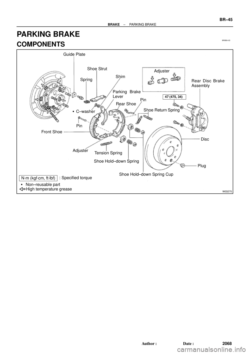
Guide Plate
SpringShoe Strut
ShimAdjuster
Rear Disc Brake
Assembly
Disc
Plug Pin
Shoe Return Spring Rear Shoe Parking Brake
Lever
�C±washer
Pin
Front Shoe
Adjuster
Tension Spring
Shoe Hold±down Spring
Shoe Hold±down Spring Cup
High temperature grease � Non±reusable part
N´m (kgf´cm, ft´lbf): Specified torque
47 (475, 34)
± BRAKEPARKING BRAKE
BR±45
2068 Author�: Date�:
PARKING BRAKE
COMPONENTS
Page 1060 of 4592

2. REMOVE REAR DISC BRAKE ASSEMBLY")
BR0B9±03
W03265
R00309
BR3948
R00310
BR±46
± BRAKEPARKING BRAKE
2069 Author�: Date�:
DISASSEMBLY
1. REMOVE REAR WHEEL
Torque: 103 N´m (1.050 kgf´cm, 76 ft´lbf)
2. REMOVE REAR DISC BRAKE ASSEMBLY
(a) Remove the 2 mounting bolts and remove the disc brake
assembly.
Torque: 47 N´m (475 kgf´cm, 34 ft´lbf)
(b) Suspend the disc brake securely. Ensure that the hose is
not stretched.
3. REMOVE DISC
Release the parking brake lever and remove the disc.
HINT:
If the disc cannot be removed easily, turn the shoe adjuster until
the wheel turns freely.
4. REMOVE SHOE RETURN SPRINGS
Using needle±nose pliers, remove the shoe return springs.
5. REMOVE FRONT SHOE ADJUSTER AND TENSION
SPRING
(a) Slide out the front shoe and remove the shoe adjuster.
(b) Remove the shoe strut with the spring.
(c) Remove the shoe hold±down spring cups, spring and pin.
(d) Disconnect the tension spring and remove the front shoe.
6. REMOVE REAR SHOE
(a) Slide out the rear shoe.
(b) Remove the tension spring from the rear shoe.
(c) Remove the shoe hold±down spring cups, spring and pin.
(d) Using needle±nose pliers, disconnect the parking brake
cable from the parking brake shoe lever.
Page 2910 of 4592
LU027±04
B06398
� Gasket RH Fender Apron Seal
PS Pump Drive Belt
A/C Compressor
Connector
A/C Compressor
No.2 RH Engine
Mounting Stay (M/T) Engine Moving
Control Rod
RH Engine Mounting Stay
No.2 RH Engine Mounting
Bracket
Ground Strap
Bracket
Front Exhaust Pipe
Stay
�
PS Pump Drive Belt
Adjusting Strut
Generator Drive Belt
Adjusting Bar Bracket
� Gasket
�
64 (650, 47)
62 (630, 46)
33 (330, 24)
21 (210, 15)
56 (570, 41)
64 (650, 47)
32 (320, 23)
62 (630, 46)
33 (330, 24)
N´m (kgf´cm, ft´lbf) : Specified torque
� Non±reusable part
Bracket
Generator Drive
Belt
Radiator Reservoir Hose
± LUBRICATION (1MZ±FE)OIL PUMP
LU±5
1669 Author�: Date�:
OIL PUMP
COMPONENTS
Page 2914 of 4592
LU028±03
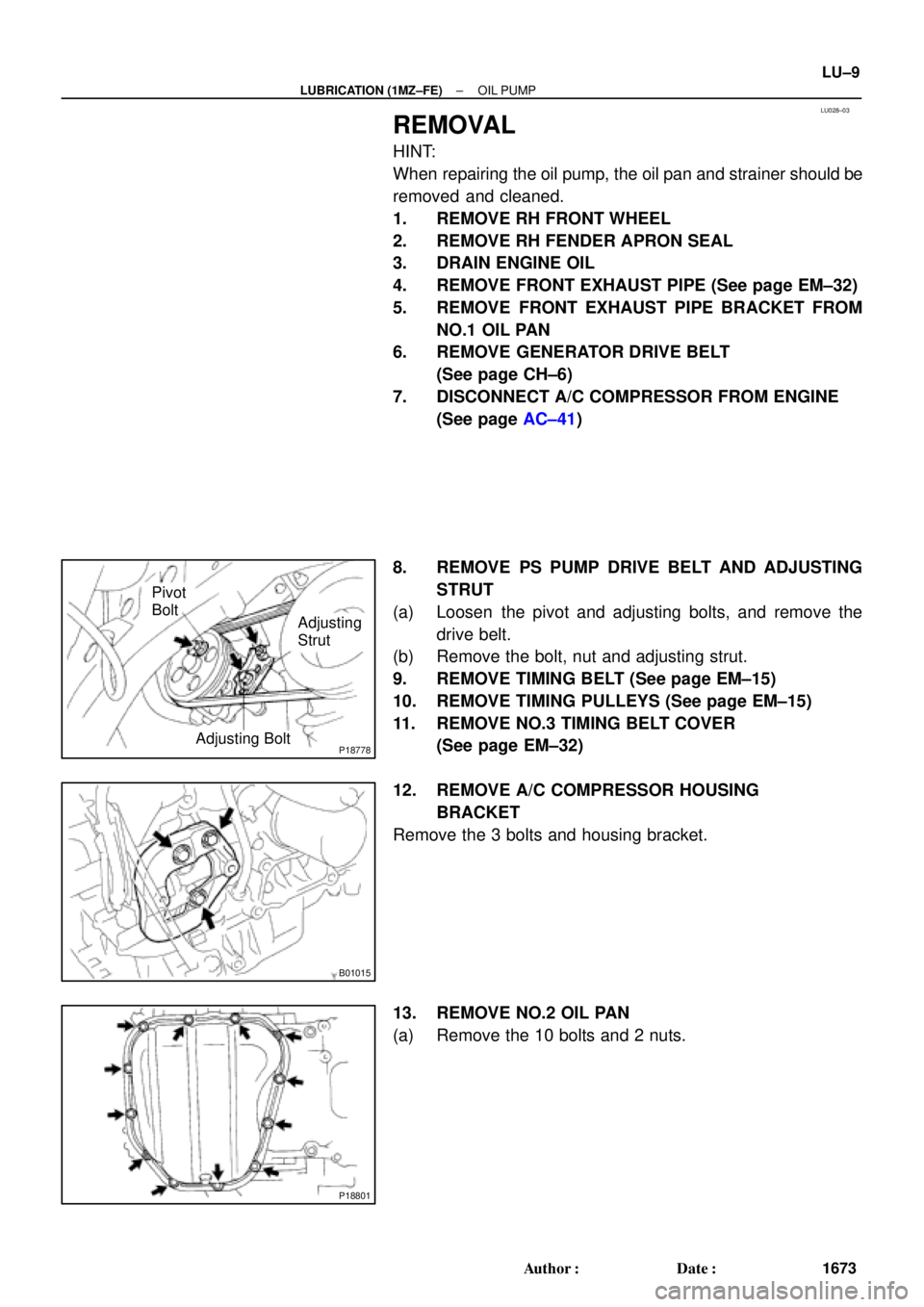
P18778Adjusting Bolt
Adjusting
Strut Pivot
Bolt
B01015
P18801
± LUBRICATION (1MZ±FE)OIL PUMP
LU±9
1673 Author�: Date�:
REMOVAL
HINT:
When repairing the oil pump, the oil pan and strainer should be
removed and cleaned.
1. REMOVE RH FRONT WHEEL
2. REMOVE RH FENDER APRON SEAL
3. DRAIN ENGINE OIL
4. REMOVE FRONT EXHAUST PIPE (See page EM±32)
5. REMOVE FRONT EXHAUST PIPE BRACKET FROM
NO.1 OIL PAN
6. REMOVE GENERATOR DRIVE BELT
(See page CH±6)
7. DISCONNECT A/C COMPRESSOR FROM ENGINE
(See page AC±41)
8. REMOVE PS PUMP DRIVE BELT AND ADJUSTING
STRUT
(a) Loosen the pivot and adjusting bolts, and remove the
drive belt.
(b) Remove the bolt, nut and adjusting strut.
9. REMOVE TIMING BELT (See page EM±15)
10. REMOVE TIMING PULLEYS (See page EM±15)
11. REMOVE NO.3 TIMING BELT COVER
(See page EM±32)
12. REMOVE A/C COMPRESSOR HOUSING
BRACKET
Remove the 3 bolts and housing bracket.
13. REMOVE NO.2 OIL PAN
(a) Remove the 10 bolts and 2 nuts.
Page 2923 of 4592
OIL PUMP
1682 Author�: Date�:
(b) Apply seal packing to the No.2 oil pan as shown in the il-
lustration.
Seal packing:
Part No. 08826�")
P12568
A
A
BB
Seal Width
4 ± 5 mm LU±18
± LUBRICATION (1MZ±FE)OIL PUMP
1682 Author�: Date�:
(b) Apply seal packing to the No.2 oil pan as shown in the il-
lustration.
Seal packing:
Part No. 08826±00080 or equivalent
�Install a nozzle that has been cut to a 4 ± 5 mm (0.16
± 0.20 in.) opening.
HINT:
Avoid applying an excessive amount to the surface.
�Parts must be assembled within 3 minutes of ap-
plication. Otherwise the material must be removed
and reapplied.
�Immediately remove nozzle from the tube and rein-
stall cap.
(c) Install the No.2 oil pan with the 10 bolts and 2 nuts. Uni-
formly tighten the bolts and nuts in several passes.
Torque: 8 N´m (80 kgf´cm, 69 in.´lbf)
7. INSTALL A/C COMPRESSOR HOUSING BRACKET
Torque: 25 N´m (250 kgf´cm, 18 ft´lbf)
8. INSTALL NO.3 TIMING BELT COVER
(See page EM±21)
9. INSTALL TIMING PULLEYS (See page EM±21)
10. INSTALL TIMING BELT (See page EM±21)
11. INSTALL ADJUSTING STRUT AND PS PUMP DRIVE
BELT
(a) Temporarily install the adjusting strut with the bolt and the
nut.
(b) Install the drive belt with the pivot and adjusting bolts.
Torque: 43.1 N´m (440 kgf´cm, 32 ft´lbf)
(c) Tighten the nut.
Torque: 43.1 N´m (440 kgf´cm, 32 ft´lbf)
12. INSTALL A/C COMPRESSOR (See page AC±47)
13. INSTALL GENERATOR DRIVE BELT
(See page CH±16)
14. INSTALL FRONT EXHAUST PIPE BRACKET TO
NO.1 OIL PAN
Torque: 21 N´m (210 kgf´cm, 15 ft´lbf)
15. INSTALL FRONT EXHAUST PIPE (See page EM±76)
16. REMOVE RH FENDER APRON SEAL
17. REMOVE RH FRONT WHEEL
18. FILL ENGINE WITH OIL
19. START ENGINE AND CHECK FOR LEAKS
20. RECHECK ENGINE OIL LEVEL
Page 3268 of 4592

193 Author�: Date�:
TORQUE SPECIFICATION
Part tightenedN´mkgf´cmft´lbf
Oil pressure switch x Cylinder block131309
No.2 oil pan x Drai")
SS07F±03
SS±30
± SERVICE SPECIFICATIONSLUBRICATION (1MZ±FE)
193 Author�: Date�:
TORQUE SPECIFICATION
Part tightenedN´mkgf´cmft´lbf
Oil pressure switch x Cylinder block131309
No.2 oil pan x Drain plug4546033
Oil pump x Relief valve plug36.837537
Oil pump x Cylinder block 10 mm head
12 mm head8
19.580
20069 in.´lbf
14
Crankshaft position sensor x Oil pump88069 in.´lbf
Oil pan baffle plate x No.1 oil pan88069 in.´lbf
No.1 oil pan x Cylinder block19.520014
No.1 oil pan x Oil pump 10 mm head
12 mm head8
19.580
20069 in.´lbf
14
No.1 oil pan x Rear oil seal retainer88069 in.´lbf
No.1 oil pan x Transaxle37.238027
Oil strainer x Main bearing cap88069 in.´lbf
Oil strainer x Oil pump88069 in.´lbf
No.2 oil pan x No.1 oil pan88069 in.´lbf
Flywheel housing under cover x Transaxle7.88069 in.´lbf
A/C compressor x A/C compressor housing bracket2525018
PS pump x PS pump bracket4344032
PS pump drive belt adjusting strut x PS pump4344032
PS pump drive belt adjusting strut x Oil pump4344032
Exhaust pipe bracket x No.1 oil pan2121015
Page 3297 of 4592

Cold tire inflationP195/70R1")
SS04W±01
± SERVICE SPECIFICATIONSSUSPENSION AND AXLE
SS±59
222 Author�: Date�:
SUSPENSION AND AXLE
SERVICE DATA
P195/70R14 90SFront, Rear*1210 kPa (2.1 kgf/cm2, 30 psi)
Cold tire inflationP195/70R14 90SFront, Rear*2210 kPa (2.1 kgf/cm2, 30 psi)pressure
(Normal driving)P205/65R15 92HFront, Rear*1220 kPa (2.2 kgf/cm2, 32 psi)(Normal driving)P205/65R15 92HFront, Rear*2200 kPa (2.0 kgf/cm2, 29 psi)
P195/70R14 90SFront, Rear*3210 kPa (2.1 kgf/cm2, 30 psi)
Cold tire inflationP195/70R14 90SFront, Rear*4240 kPa (2.4 kgf/cm2, 35 psi)pressure
(Trailer towing)P205/65R15 92HFront, Rear*3220 kPa (2.2 kgf/cm2, 32 psi)(Trailer towing)P205/65R15 92HFront, Rear*4240 kPa (2.4 kgf/cm2, 35 psi)
V hi l h i ht 195/70R14Front*5212 mm (8.35 in.)Vehicle height195/70R14Rear*6264 mm (10.39 in.)
205/65R15Front*5215 mm (8.46 in.)205/65R15Rear*6266 mm (10.49 in.)
Camber 5S±FE±0°36'±45'(0.6°±0.75°)Camber 5S ± FE
1MZ ± FE
±036 ± 45 (0.6 ± 0.75)
±0°37' ± 45' (0.62° ± 0.75°)1MZ ± FE±037 ± 45 (0.62 ± 0.75)
Left ± right error45' (0.75°) or less
Front wheel
alignment
Caster 5S ± FE
1MZ ± FE
Left ± right error2°10' ± 45' (2.17° ± 0.75°)
2°11' ± 45' (2.18° ± 0.75°)
45' (0.75°) or less
alignmentSteering axis inclination 5S ± FE
1MZ ± FE
Left ± right error13°01' ± 45' (13.02° ± 0.75°)
13°04' ± 45' (13.07° ± 0.75°)
45' (0.75°) or less
Toe±in (Total)
Rack end length difference0° ± 12' (0° ± 0.2°)
0 ± 2 mm (0 ± 0.08 in.)
1.5 mm (0.059 in.) or less
Wh l l 195/70R14Inside wheel 37°12' ± 2° (37.2° ± 2°)Wheel angle195/70R14Outside wheel 32°21' (32.45°)
205/65R15Inside wheel 35°47' ± 2° (35.78° ± 2°)205/65R15Outside wheel 31°25' (31.42°)
Rear wheel
li t
Camber 5S ± FE
1MZ ± FE
Left ± right error±0°42' ± 45' (±0.7° ± 0.75°)
±0°45' ± 45' (±0.75° ± 0.75°)
45' (0.75°) or less
alignmentToe±in (Total)
No.2 lower suspension arm length difference0°24' ± 12' (0.4° ± 0.2°)
4 ± 2 mm (0.16 ± 0.08 in.)
1 mm (0.04 in.) or less
*1: For all loads including rated loads
*2: For reduced loads (1 to 4 passengers)
*3: For driving under 160 km/h (100 mph)
*4: For driving at 160 km/h (100 mph) or over
*5: Front measuring point
Measure from the ground to the center of the front side lower suspension arm mounting bolt.
*6: Rear measuring point
Measure from the ground to the center of the strut rod mounting bolt.
Page 3299 of 4592

SS04X±01
± SERVICE SPECIFICATIONSSUSPENSION AND AXLE
SS±61
224 Author�: Date�:
TORQUE SPECIFICATION
Part tightenedN´mkgf´cmft´lbf
FRONT:
Hub nut1031,05076
Tie rod end lock nut7475054
Steering knuckle x Shock absorber2112,150156
Steering knuckle x Brake caliper1071,09079
Steering knuckle x Tie rod end4950036
Axle hub x Drive shaft2943,000217
Lower ball joint x Lower suspension arm1271,30094
Lower ball joint x Steering knuckle1231,25090
Steering knuckle x Disc brake dust cover8.38574 in.´lbf
Drive shaft center bearing lock bolt3233024
Suspension support x Body8082059
Suspension support x Piston rod4950036
ABS speed sensor set bolt8.08271 in.´lbf
Flexible hose and ABS speed sensor wire harness x Shock absorber2930022
Lower suspension arm set bolt2062,100152
Stabilizer bar bracket x Suspension member1919514
Stabilizer bar link set bolt3940029
REAR:
Hub nut1031,05076
No.2 lower suspension arm lock nut5657041
Brake caliper x Rear axle carrier4747534
Axle hub bearing set bolt8082059
Shock absorber x Rear axle carrier New nut
Reused nut (apply engine oil the threads)255
1962,600
2,000188
145
Flexible hose x Shock absorber2930022
ABS speed sensor set bolt8.08271 in.´lbf
ABS speed sensor wire harness x Shock absorber5.55649 in.´lbf
Rear side seatback set bolt1818513
Suspension support x Body3940029
Suspension support x Piston rod4950036
Exhaust center pipe set nut5657041
Parking brake cable set bolt5.45548 in.´lbf
Lower suspension arm x Suspension member1811,850134
Lower suspension arm x Rear axle carrier1811,850134
Strut rod x Body11 31,15083
Strut rod x Rear axle carrier11 31,15083
Suspension member x Body5152038
Suspension member lower stopper sub±assembly x Body3839028
Stabilizer bar bracket x Suspension member1919514
Stabiliser bar link set nut3940029