Page 278 of 4592
AUTOMATIC TRANSAXLECOMPONENT PARTS INSTALLATION ±
AX±108
3. INSTALL PARKING LOCK ROD
4. INSTALL PARKING LOCK PAWL BRACKET
Torque: 7.4 N´m (75 kgf´cm, 65 in.´lbf)
5. CHECK OPERATION OF PARKING LOCK PAWL
Make sure the counter driven gear is locked when the
manual valve lever is in the P position.
6. INSTALL FIRST AND REVERSE BRAKE PISTON TO
TRANSMISSION CASE
(a) Coat a new O±rings with ATF.
(b) Install the 2 O±rings on the piston.
(c) Push the piston into the bore of the case, facing the spring
seat upward.
Page 414 of 4592
AUTOMATIC TRANSAXLECOMPONENT PARTS INSTALLATION ±
AX±108
14. INSTALL DRIVE PINION CAP
(a) Install a new O±ring to the cap.
(b) Install the drive pinion cap to the transaxle case.
4±SPEED GEAR UNIT INSTALLATION
1. INSTALL PARKING LOCK PAWL
(a) Place the parking lock pawl onto the case.
Hook the spring ends to the case and pawl.
(b) Instal the pin into the hole of the case through the spring
and pawl.
2. INSTALL MANUAL VALVE SHAFT
(a) Coat the oil seal lip with MP grease.
(b) Install the manual valve shaft oil seal to the case.
(c) Assembly a new collar to the manual valve lever.
(d) Install the manual valve shaft to the transmission case
through the manual lever.
(e) Install the parking lock rod.
AX0U2±03
Page 557 of 4592
AUTOMATIC TRANSAXLECOMPONENT PARTS INSTALLATION ±
AX±108
14. INSTALL DRIVE PINION CAP
(a) Install a new O±ring to the cap.
(b) Install the drive pinion cap to the transaxle case.
4±SPEED GEAR UNIT INSTALLATION
1. INSTALL PARKING LOCK PAWL
(a) Place the parking lock pawl onto the case.
Hook the spring ends to the case and pawl.
(b) Instal the pin into the hole of the case through the spring
and pawl.
2. INSTALL MANUAL VALVE SHAFT
(a) Coat the oil seal lip with MP grease.
(b) Install the manual valve shaft oil seal to the case.
(c) Assembly a new collar to the manual valve lever.
(d) Install the manual valve shaft to the transmission case
through the manual lever.
(e) Install the parking lock rod.
AX0U2±03
Page 1217 of 4592

N09214
S05347
± DIAGNOSTICSENGINE (5S±FE)
DI±5
240 Author�: Date�:
(b) Check the DLC3
The vehicle's ECM uses ISO 9141±2 for communication.
The terminal arrangement of DLC3 complies with SAE
J1962 and matches the ISO 9141±2 format.
Terminal No.Connection / Voltage or ResistanceCondition
7Bus � Line / Pulse generationDuring transmission
4Chassis Ground e Body Ground /1 W or lessAlways
5Signal Ground e Body Ground /1 W or lessAlways
16Battery Positive e Body Ground /9 ~ 14 VAlways
HINT:
If your display shows ºUNABLE TO CONNECT TO VEHICLEº
when you have connected the cable of the OBD II scan tool or
TOYOTA hand±held tester to DLC3, turned the ignition switch
ON and operated the scan tool, there is a problem on the ve-
hicle side or tool side.
�If communication is normal when the tool is connected to
another vehicle, inspect DLC3 on the original vehicle.
�If communication is still not possible when the tool is con-
nected to another vehicle, the problem is probably in the
tool itself, so consult the Service Department listed in the
tool's instruction manual.
2. INSPECT DIAGNOSIS (Normal Mode)
(a) Check the MIL.
(1) The MIL comes on when the ignition switch is turned
ON and the engine is not running.
HINT:
If the MIL does not light up, troubleshoot the combination meter
(See page BE±2).
(2) When the engine started, the MIL should go off. If
the lamp remains on, the diagnosis system has de-
tected a malfunction or abnormality in the system.
(b) Check the DTC.
NOTICE:
TOYOTA hand±held tester only: When the diagnosis sys-
tem is switched from normal mode to check mode, it
erases all DTCs and freezed frame data recorded in normal
mode. So before switching modes, always check the DTCs
and freezed frame data, and note them down.
(1) Prepare the OBD II scan tool (complying with SAE
J1978) or TOYOTA hand±held tester.
Page 1411 of 4592

N09214
DLC3
S04159
± DIAGNOSTICSENGINE (1MZ±FE)
DI±199
434 Author�: Date�:
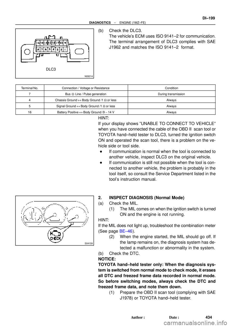
(b) Check the DLC3.
The vehicle's ECM uses ISO 9141±2 for communication.
The terminal arrangement of DLC3 complies with SAE
J1962 and matches the ISO 9141±2 format.
Terminal No.Connection / Voltage or ResistanceCondition
7Bus � Line / Pulse generationDuring transmission
4Chassis Ground e Body Ground /1 W or lessAlways
5Signal Ground e Body Ground /1 W or lessAlways
16Battery Positive e Body Ground /9 ~ 14 VAlways
HINT:
If your display shows ºUNABLE TO CONNECT TO VEHICLEº
when you have connected the cable of the OBD II scan tool or
TOYOTA hand±held tester to DLC3, turned the ignition switch
ON and operated the scan tool, there is a problem on the ve-
hicle side or tool side.
�If communication is normal when the tool is connected to
another vehicle, inspect DLC3 on the original vehicle.
�If communication is still not possible when the tool is con-
nected to another vehicle, the problem is probably in the
tool itself, so consult the Service Department listed in the
tool's instruction manual.
2. INSPECT DIAGNOSIS (Normal Mode)
(a) Check the MIL.
(1) The MIL comes on when the ignition switch is turned
ON and the engine is not running.
HINT:
If the MIL does not light up, troubleshoot the combination meter
(See page BE±46).
(2) When the engine started, the MIL should go off. If
the lamp remains on, the diagnosis system has de-
tected a malfunction or abnormality in the system.
(b) Check the DTC.
NOTICE:
TOYOTA hand±held tester only: When the diagnosis sys-
tem is switched from normal mode to check mode, it erases
all DTC and freezed frame data recorded in normal mode.
So before switching modes, always check the DTC and
freezed frame data, and note them down.
(1) Prepare the OBD II scan tool (complying with SAE
J1978) or TOYOTA hand±held tester.
Page 2156 of 4592

A04550
DLC3
1
234
56
7
8
9
10 11 12 13 1415
16
S05347
± DIAGNOSTICSENGINE
DI±5
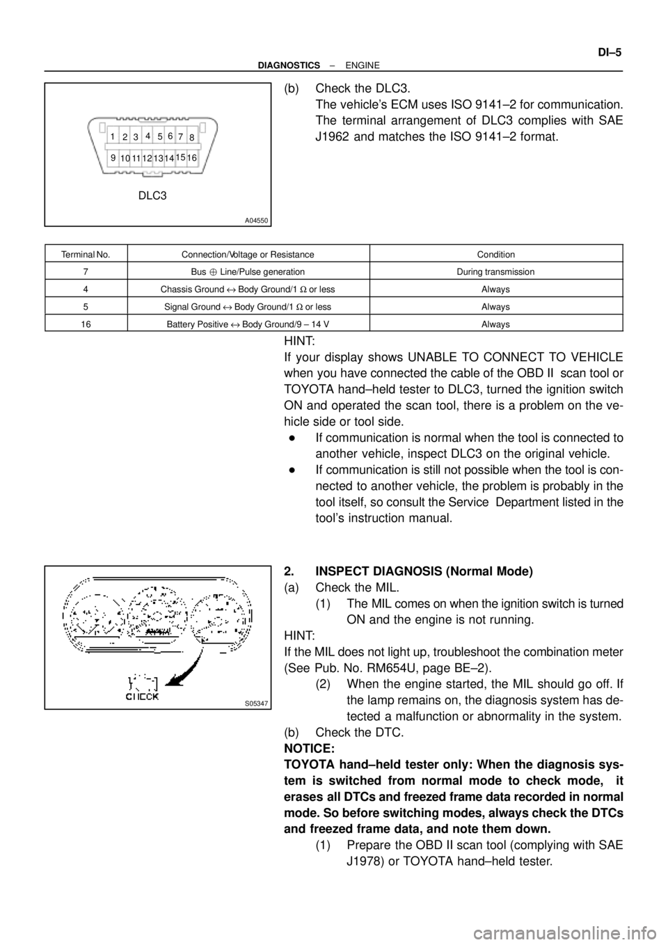
(b) Check the DLC3.
The vehicle's ECM uses ISO 9141±2 for communication.
The terminal arrangement of DLC3 complies with SAE
J1962 and matches the ISO 9141±2 format.
Terminal No.Connection/Voltage or ResistanceCondition
7Bus � Line/Pulse generationDuring transmission
4Chassis Ground e Body Ground/1 W or lessAlways
5Signal Ground e Body Ground/1 W or lessAlways
16Battery Positive e Body Ground/9 ± 14 VAlways
HINT:
If your display shows UNABLE TO CONNECT TO VEHICLE
when you have connected the cable of the OBD II scan tool or
TOYOTA hand±held tester to DLC3, turned the ignition switch
ON and operated the scan tool, there is a problem on the ve-
hicle side or tool side.
�If communication is normal when the tool is connected to
another vehicle, inspect DLC3 on the original vehicle.
�If communication is still not possible when the tool is con-
nected to another vehicle, the problem is probably in the
tool itself, so consult the Service Department listed in the
tool's instruction manual.
2. INSPECT DIAGNOSIS (Normal Mode)
(a) Check the MIL.
(1) The MIL comes on when the ignition switch is turned
ON and the engine is not running.
HINT:
If the MIL does not light up, troubleshoot the combination meter
(See Pub. No. RM654U, page BE±2).
(2) When the engine started, the MIL should go off. If
the lamp remains on, the diagnosis system has de-
tected a malfunction or abnormality in the system.
(b) Check the DTC.
NOTICE:
TOYOTA hand±held tester only: When the diagnosis sys-
tem is switched from normal mode to check mode, it
erases all DTCs and freezed frame data recorded in normal
mode. So before switching modes, always check the DTCs
and freezed frame data, and note them down.
(1) Prepare the OBD II scan tool (complying with SAE
J1978) or TOYOTA hand±held tester.
Page 2161 of 4592

A07370S05309A07664
E1 TE1
SST
DLC1
A09429
DI±10
± DIAGNOSTICSENGINE
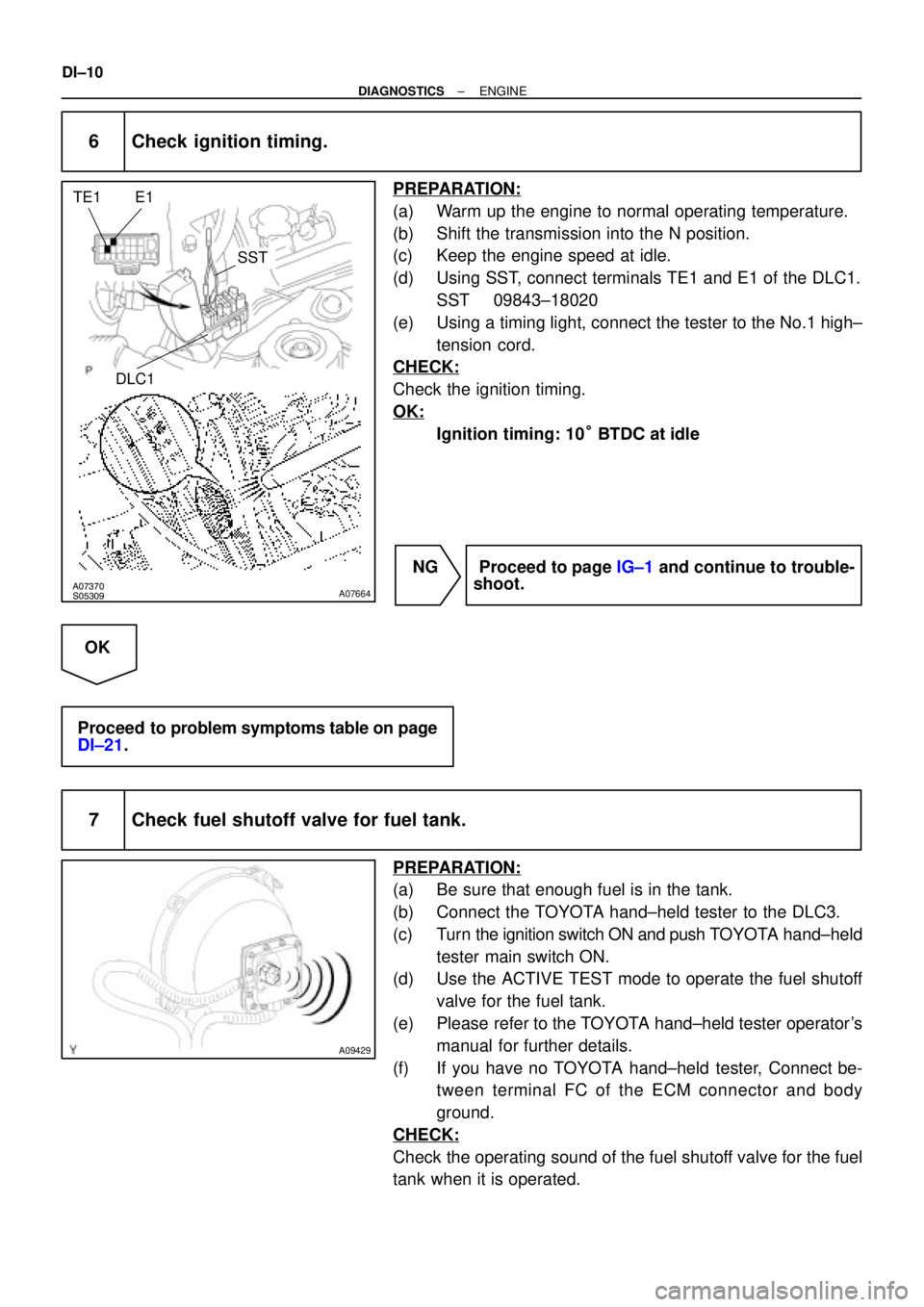
6 Check ignition timing.
PREPARATION:
(a) Warm up the engine to normal operating temperature.
(b) Shift the transmission into the N position.
(c) Keep the engine speed at idle.
(d) Using SST, connect terminals TE1 and E1 of the DLC1.
SST 09843±18020
(e) Using a timing light, connect the tester to the No.1 high±
tension cord.
CHECK:
Check the ignition timing.
OK:
Ignition timing: 10° BTDC at idle
NG Proceed to page IG±1 and continue to trouble-
shoot.
OK
Proceed to problem symptoms table on page
DI±21.
7 Check fuel shutoff valve for fuel tank.
PREPARATION:
(a) Be sure that enough fuel is in the tank.
(b) Connect the TOYOTA hand±held tester to the DLC3.
(c) Turn the ignition switch ON and push TOYOTA hand±held
tester main switch ON.
(d) Use the ACTIVE TEST mode to operate the fuel shutoff
valve for the fuel tank.
(e) Please refer to the TOYOTA hand±held tester operator's
manual for further details.
(f) If you have no TOYOTA hand±held tester, Connect be-
tween terminal FC of the ECM connector and body
ground.
CHECK:
Check the operating sound of the fuel shutoff valve for the fuel
tank when it is operated.
Page 2560 of 4592

EM080±03
S05331
A07370
SST
E1
TE1
S05309
± ENGINE MECHANICAL (5S±FE)IGNITION TIMING
EM±9
1181 Author�: Date�:
IGNITION TIMING
INSPECTION
1. WARM UP ENGINE
Allow the engine to warm up to normal operating temperature.
2. CONNECT TOYOTA HAND±HELD TESTER OR OBDII
SCAN TOOL
(a) Remove the fuse cover on the instrument panel.
(b) Connect a TOYOTA hand±held tester or OBDII scan tool
to the DLC3.
(c) Please refer to the TOYOTA hand±held tester or OBDII
scan tool operator's manual for further details.
3. CONNECT TIMING LIGHT TO ENGINE
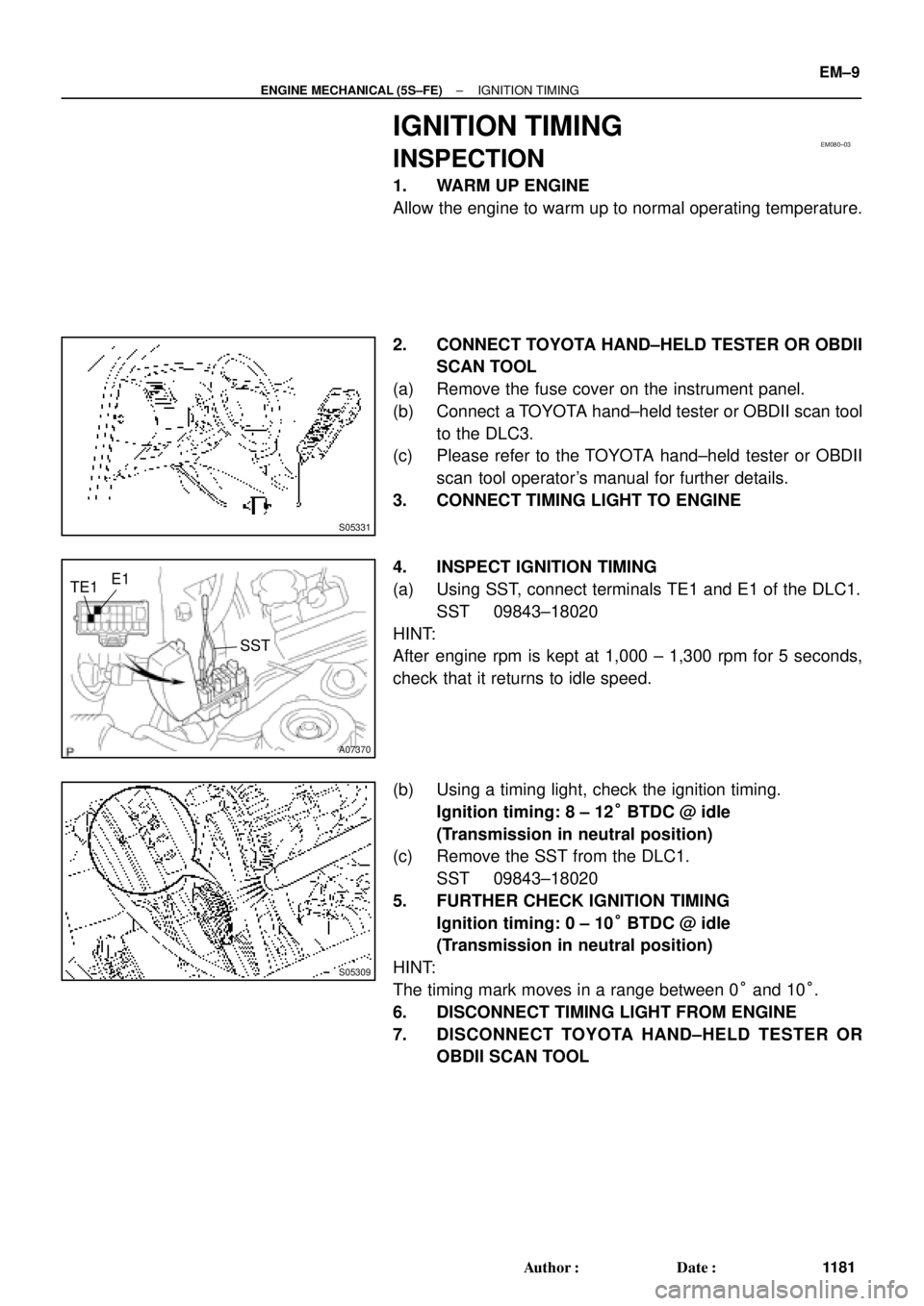
4. INSPECT IGNITION TIMING
(a) Using SST, connect terminals TE1 and E1 of the DLC1.
SST 09843±18020
HINT:
After engine rpm is kept at 1,000 ± 1,300 rpm for 5 seconds,
check that it returns to idle speed.
(b) Using a timing light, check the ignition timing.
Ignition timing: 8 ± 12° BTDC @ idle
(Transmission in neutral position)
(c) Remove the SST from the DLC1.
SST 09843±18020
5. FURTHER CHECK IGNITION TIMING
Ignition timing: 0 ± 10° BTDC @ idle
(Transmission in neutral position)
HINT:
The timing mark moves in a range between 0° and 10°.
6. DISCONNECT TIMING LIGHT FROM ENGINE
7. DISCONNECT TOYOTA HAND±HELD TESTER OR
OBDII SCAN TOOL