Page 117 of 4592
Q10172
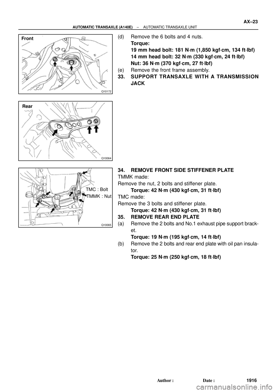
Front
Q10064
Rear
Q10065
TMC : Bolt
TMMK : Nut
± AUTOMATIC TRANSAXLE (A140E)AUTOMATIC TRANSAXLE UNIT
AX±23
1916 Author�: Date�:
(d) Remove the 6 bolts and 4 nuts.
Torque:
19 mm head bolt: 181 N´m (1,850 kgf´cm, 134 ft´lbf)
14 mm head bolt: 32 N´m (330 kgf´cm, 24 ft´lbf)
Nut: 36 N´m (370 kgf´cm, 27 ft´lbf)
(e) Remove the front frame assembly.
33. SUPPORT TRANSAXLE WITH A TRANSMISSION
JACK
34. REMOVE FRONT SIDE STIFFENER PLATE
TMMK made:
Remove the nut, 2 bolts and stiffener plate.
Torque: 42 N´m (430 kgf´cm, 31 ft´lbf)
TMC made:
Remove the 3 bolts and stiffener plate.
Torque: 42 N´m (430 kgf´cm, 31 ft´lbf)
35. REMOVE REAR END PLATE
(a) Remove the 2 bolts and No.1 exhaust pipe support brack-
et.
Torque: 19 N´m (195 kgf´cm, 14 ft´lbf)
(b) Remove the 2 bolts and rear end plate with oil pan insula-
tor.
Torque: 25 N´m (250 kgf´cm, 18 ft´lbf)
Page 149 of 4592
AUTOMATIC TRANSAXLE UNIT
1948 Author�: Date�:
(d) Remove the 6 bolts and 4 nuts.
Torque:
19 mm head bo")
Q10172
Front
Q10064
Rear
Q04660
Q10036
Z14284
Left and lower AX±28
± AUTOMATIC TRANSAXLE (A541E)AUTOMATIC TRANSAXLE UNIT
1948 Author�: Date�:
(d) Remove the 6 bolts and 4 nuts.
Torque:
19 mm head bolt: 181 N´m (1,850 kgf´cm, 134 ft´lbf)
14 mm head bolt: 32 N´m (330 kgf´cm, 24 ft´lbf)
Nut: 36 N´m (370 kgf´cm, 27 ft´lbf)
(e) Remove the front frame assembly.
33. SUPPORT TRANSAXLE WITH A TRANSMISSION
JACK
34. REMOVE TORQUE CONVERTER CLUTCH MOUNT-
ING BOLTS
Turn the crankshaft to gain access to each bolt, remove the 6
bolts with holding the crankshaft pulley bolt by a wrench.
Torque: 41 N´m (420 kgf´cm, 30 ft´lbf)
HINT:
At the time of installation, please refer to the following item.
First install black colored bolt and then the 5 other bolts.
35. REMOVE EXHAUST MANIFOLD PLATE
(a) Remove the bolt, nut and exhaust manifold plate.
Torque:
Except California: 20 N´m (200 kgf´cm, 15 ft´lbf)
California: 34 N´m (350 kgf´cm, 25 ft´lbf)
36. REMOVE 3 LOWER TRANSAXLE±TO±ENGINE
BOLTS
Torque: 46 N´m (470 kgf´cm, 34 ft´lbf)
37. REMOVE TRANSAXLE ASSEMBLY
Separate the transaxle and engine, and lower the transaxle.
Page 174 of 4592
Connects overdrive sun gear and overdrive carrier
O/D Brake (B0)Prevents overdrive sun gear from")
AUTOMATIC TRANSAXLEOPERATION ±
AX±4
1. FUNCTION OF COMPONENTS
FUNCTIONOPERATION
O/D Direct Clutch (C0)Connects overdrive sun gear and overdrive carrier
O/D Brake (B0)Prevents overdrive sun gear from turning either clockwise or
counterclockwise
O/D One±way Clutch (F0)When transmission is being driven by engine, connects overdrive sun
gear and overdrive carrier.
Front Clutch (C1)Connects input shaft and intermediate shaft
Rear Clutch (C2)Connects input shaft and front and rear planetary sun gears
No.1 Brake (B1)Prevents front and rear planetary sun gears from turning either clockwise
or counterclockwise
No.2 Brake (B2)Prevents outer race of F1 from turning either clockwise or counterclockwise, thus
previnting front and rear planetary sun gears from turning counterclockwise
No.3 Brake (B3)Prevents front planetary carrier from turning either clockwise or counterclockwise
No.1 One±way Clutch (F1)When B2 is operating prevents front and rear planetary sun gears from turning
counterclockwise
No.2 One±way Clutch (F2)Prevents front planetary carrier from turning counterclockwise
Page 178 of 4592
AUTOMATIC TRANSAXLEPREPARATION ±
AX±8
PREPARATION
SST (SPECIAL SERVICE TOOLS)
09240±00020Wire Gauge Set
09330±00021Companion Flange Holding Tool
09350±32014TOYOTA Automatic Transmission
Tool Set
09308±10010Oil Seal Puller
(09351±32020)Stator Stopper
(09351±32032)Counter Driven Gear Holding Tool
(09351±32040)No.1 Piston Spring Compressor
(09351±32050)Snap Ring Expander
(09351±32061)Oil Pump Puller
(09351±32070)No.2 Piston Spring Compressor
(09351±32080)Lock Nut Wrench
(09351±32090)Oil Seal Remover & Replacer
(09351±32100)Drive Pinion Bearing Replacer
AX0EQ±02
Page 186 of 4592
AUTOMATIC TRANSAXLECOMPONENT PARTS REMOVAL ±
AX±16
(b) Remove the cover.
7. REMOVE OIL PAN AND GASKET
(a) Remove the 15 bolts.
(b) Remove the oil pan by lifting transaxle case.
NOTICE: Do not turn the transaxle over as this will contami-
nate the valve body with the foreign materials in the bottom
of the oil pan.
(c) Place the transaxle on wooden blocks to prevent damage
to the tube bracket.
8. EXAMINE PARTICLES IN PAN
Remove the magnets and use them to collect any steel
chips. Look carefully at the chips and particles in the oil
pan and on the magnets to anticipate what type of wear
you will find in the transmission:
Steel (magnetic): bearing, gear and plate wear
Brass (non±magnetic): bushing wear
9. DISCONNECT NO.1 AND NO.2 SOLENOID CONNEC-
TORS
10. REMOVE TUBE BRACKET AND OIL STRAINER
Page 191 of 4592
AUTOMATIC TRANSAXLECOMPONENT PARTS REMOVAL ±
AX±21
29. REMOVE BEARING RACES FROM FRONT PLAN-
ETARY RING GEAR
30. REMOVE PLANETARY GEAR
31. REMOVE RACES AND BEARINGS FROM PLAN-
ETARY GEAR
32. REMOVE SUN GEAR, SUN GEAR INPUT DRUM, SE-
COND BRAKE HUB AND NO.1 ONE±WAY CLUTCH
33. STAND TRANSMISSION CASE UP AND REMOVE SE-
COND COAST BRAKE BAND GUIDE
Page 202 of 4592

AUTOMATIC TRANSAXLECOMPONENT PARTS ±
AX±32
COMPONENT PARTS
GENERAL NOTES
The instructions here are organized so that you work on only one component group at a time.
This will help avoid confusion from similar±looking parts of different subassemblies being on your work-
bench at the same time.
The component groups are inspected and repaired from the converter housing side.
As much as possible, complete the inspection, repair and assembly before proceeding to the next com-
ponent group. If a component group cannot be assembled because parts are being ordered, be sure
to keep all parts of that group in a separate container while proceeding with disassembly, inspection,
repair and assembly of other component groups.
Recommended fluid for the automatic transaxle:
DEXRON ® @@@@@: [g 2]
GENERAL CLEANING NOTES:
1. All disassembled parts should be washed clean and any fluid passages and holes blown through with
compressed air.
2. When using compressed air to dry parts, always aim away from yourself to prevent accidentally spray-
ing automatic transmission fluid or kerosene in your face.
3. The recommended automatic transaxle fluid or kerosene should be used for cleaning.
PARTS ARRANGEMENT:
1. After cleaning, the parts should be arranged in the correct order to allow efficient inspection, repairs,
and reassembly.
2. When disassembling a valve body, be sure to keep each valve together with the corresponding spring.
3. New brakes and clutches that are to be used for replacement must be soaked in transaxle fluid for at
least 15 minutes before assembly.
GENERAL ASSEMBLY:
1. All oil seal rings, clutch discs, clutch plates, rotating parts, and sliding surfaces should be coated with
transmission fluid prior to reassembly.
2. All gaskets and rubber O±rings should be replaced.
3. Make sure that the ends of a snap ring are not aligned with one of the cutouts and are installed in the
groove correctly.
4. If a worn bushing is to be replaced, the subassembly containing that bushing must be replaced.
5. Check thrust bearings and races for wear or damage. Replace if necessary.
6. Use petroleum jelly to keep parts in place.
AX0EY±02
Page 278 of 4592
AUTOMATIC TRANSAXLECOMPONENT PARTS INSTALLATION ±
AX±108
3. INSTALL PARKING LOCK ROD
4. INSTALL PARKING LOCK PAWL BRACKET
Torque: 7.4 N´m (75 kgf´cm, 65 in.´lbf)
5. CHECK OPERATION OF PARKING LOCK PAWL
Make sure the counter driven gear is locked when the
manual valve lever is in the P position.
6. INSTALL FIRST AND REVERSE BRAKE PISTON TO
TRANSMISSION CASE
(a) Coat a new O±rings with ATF.
(b) Install the 2 O±rings on the piston.
(c) Push the piston into the bore of the case, facing the spring
seat upward.

09240±00020Wire Gauge Set
09330±00021Companion Flange Holding Tool
09350±32014TOYOTA Automatic Transmission
Tool Set")
 Remove the cover.
7. REMOVE OIL PAN AND GASKET
(a) Remove the 15 bolts.
(b) Remove the oil pan by lifting transaxle case.
NOTICE: Do not turn t")


5. CHECK OPERATION OF PARKING LOC")