Page 1583 of 4592
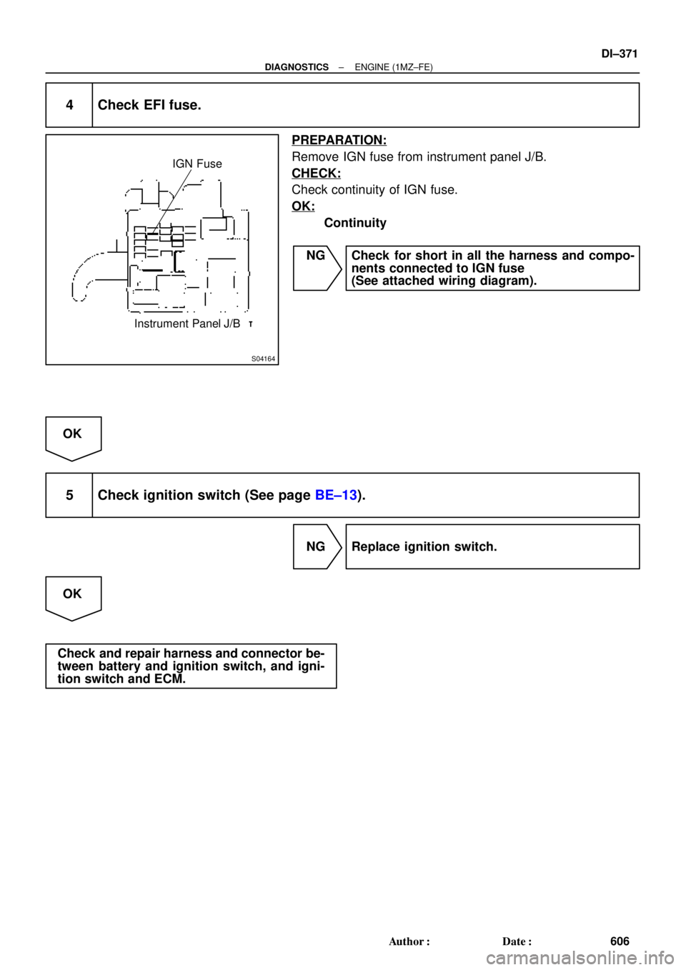
S04164
IGN Fuse
Instrument Panel J/B
± DIAGNOSTICSENGINE (1MZ±FE)
DI±371
606 Author�: Date�:
4 Check EFI fuse.
PREPARATION:
Remove IGN fuse from instrument panel J/B.
CHECK:
Check continuity of IGN fuse.
OK:
Continuity
NG Check for short in all the harness and compo-
nents connected to IGN fuse
(See attached wiring diagram).
OK
5 Check ignition switch (See page BE±13).
NG Replace ignition switch.
OK
Check and repair harness and connector be-
tween battery and ignition switch, and igni-
tion switch and ECM.
Page 1584 of 4592
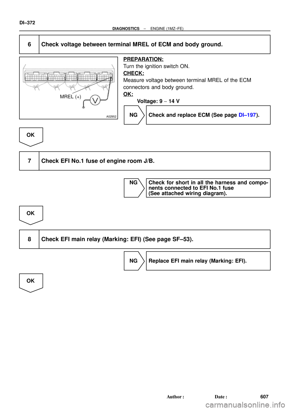
A02952
MREL (+)
DI±372
± DIAGNOSTICSENGINE (1MZ±FE)
607 Author�: Date�:
6 Check voltage between terminal MREL of ECM and body ground.
PREPARATION:
Turn the ignition switch ON.
CHECK:
Measure voltage between terminal MREL of the ECM
connectors and body ground.
OK:
Voltage: 9 ~ 14 V
NG Check and replace ECM (See page DI±197).
OK
7 Check EFI No.1 fuse of engine room J/B.
NG Check for short in all the harness and compo-
nents connected to EFI No.1 fuse
(See attached wiring diagram).
OK
8 Check EFI main relay (Marking: EFI) (See page SF±53).
NG Replace EFI main relay (Marking: EFI).
OK
Page 1733 of 4592
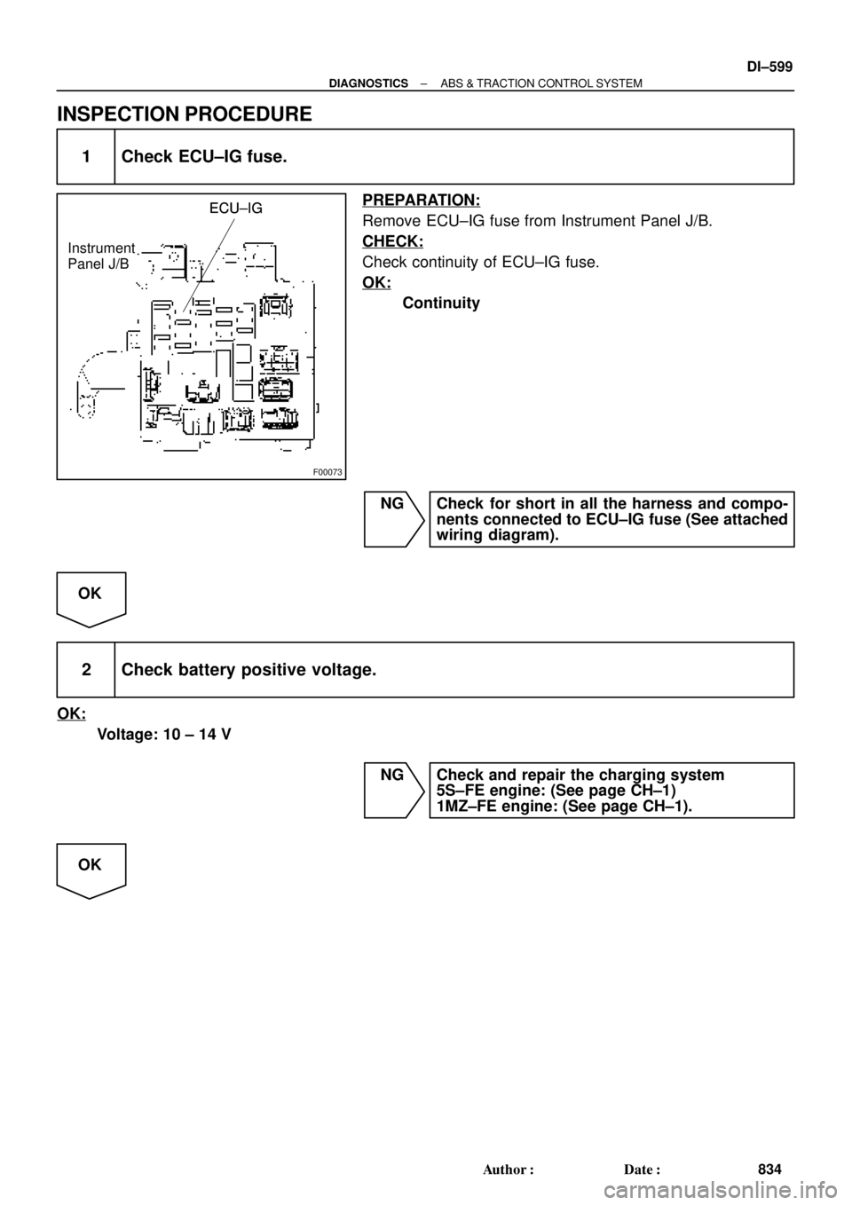
F00073
ECU±IGECU±IG
Instrument
Panel J/BECU±IG
± DIAGNOSTICSANTI±LOCK BRAKE SYSTEM (DENSO Made)
DI±521
756 Author�: Date�:
INSPECTION PROCEDURE
1 Check ECU±IG fuse.
PREPARATION:
Remove ECU±IG fuse from Instrument Panel J/B.
CHECK:
Check continuity of ECU±IG fuse.
OK:
Continuity
NG Check for short circuit in all the harness and
components connected to ECU±IG fuse (See at-
tached wiring diagram).
OK
2 Check battery positive voltage.
OK:
Voltage: 10 ± 14 V
NG Check and repair the charging system
5S±FE engine: (See page CH±1)
1MZ±FE engIne: (See page CH±1).
OK
Page 1771 of 4592
F00073
ECU±IG
Instrument
Panel J/BECU±IG
Instrument
Panel J/BECU±IG
Instrument
Panel J/B
± DIAGNOSTICSANTI±LOCK BRAKE SYSTEM (BOSCH Made)
DI±559
794 Author�: Date�:
INSPECTION PROCEDURE
1 Check ECU±IG fuse.
PREPARATION:
Remove ECU±IG fuse from Instrument Panel J/B.
CHECK:
Check continuity of ECU±IG fuse.
OK:
Continuity
NG Check for short circuit in all the harness and
components connected to ECU±IG fuse (See
the attached wiring diagram.)
OK
2 Check battery positive voltage.
OK:
Voltage: 10 ± 14 V
NG Check and repair the charging system
5S±FE engine: (See page CH±1)
1MZ±FE engine: (See page CH±1).
OK
Page 1777 of 4592
F00096
J/C
J4 D
ABS 7
C
R±LC10
1D
GAUGE
A6 4
DLC2ECU
Instrument
Panel J/BABS
Warning
Light
210
IG312
C10
DR±L R±L
WA 21
14 R±LJ/C
J29
C
C R±L
R±LR±L
IK3
± DIAGNOSTICSANTI±LOCK BRAKE SYSTEM (BOSCH Made)
DI±565
800 Author�: Date�:
ABS Warning Light Circuit
CIRCUIT DESCRIPTION
If the ECU detects any trouble, it lights the ABS warning light while at the same time prohibiting ABS control.
At this time, the ECU records a DTC in memory.
Connect terminals Tc and E
1 of the DLC1 or DLC2 to make the ABS warning light blink and output the DTC.
WIRING DIAGRAM
INSPECTION PROCEDURE
Troubleshoot in accordance with the chart below for each trouble symptom
ABS warning light does not light upGo to step 1
ABS warning light remains onGo to step 2
1 Check ABS warning light.
See combination meter troubleshooting on page BE±2.
NG Repair bulb or combination meter assembly.
OK
Check for open circuit in harness and connector between GAUGE fuse, DLC2 and ABS ECU
(See page IN±31).
DI048±08
Page 1811 of 4592
F00073
ECU±IGECU±IG
Instrument
Panel J/BECU±IG
± DIAGNOSTICSABS & TRACTION CONTROL SYSTEM
DI±599
834 Author�: Date�:
INSPECTION PROCEDURE
1 Check ECU±IG fuse.
PREPARATION:
Remove ECU±IG fuse from Instrument Panel J/B.
CHECK:
Check continuity of ECU±IG fuse.
OK:
Continuity
NG Check for short in all the harness and compo-
nents connected to ECU±IG fuse (See attached
wiring diagram).
OK
2 Check battery positive voltage.
OK:
Voltage: 10 ± 14 V
NG Check and repair the charging system
5S±FE engine: (See page CH±1)
1MZ±FE engine: (See page CH±1).
OK
Page 2004 of 4592

CIRCUIT DES")
N14677
Fuse
DI±792
± DIAGNOSTICSSUPPLEMENTAL RESTRAINT SYSTEM
1027 Author�: Date�:
SRS Warning Light Circuit Malfunction (Does not light up, when
ignition switch is turned to ACC or ON.)
CIRCUIT DESCRIPTION
The SRS warning light is located on the combination meter.
When the SRS is normal, the SRS warning light lights up for approx. 6 seconds after the ignition switch is
turned from LOCK position to ACC or ON position, and then turns off automatically.
If there is a malfunction in the SRS, the SRS warning light lights up to inform the driver of the abnormality.
When terminals Tc and E1 of the DLC1 are connected, the DTC is displayed by blinking the SRS warning
light.
WIRING DIAGRAM
See page DI±790.
INSPECTION PROCEDURE
1 Check ECU±B Fuse.
PREPARATION:
Remove ECU±B fuse.
CHECK:
Check continuity of ECU±B fuse.
OK:
Continuity
HINT:
�Fuse may be burnt out even if it appears to be OK during
visual inspection.
�If fuse is OK, install it.
NG Go to step 5.
OK
2 Prepare for inspection. (See step 1 on page DI±787)
DI1BP±08
Page 2023 of 4592
N14677
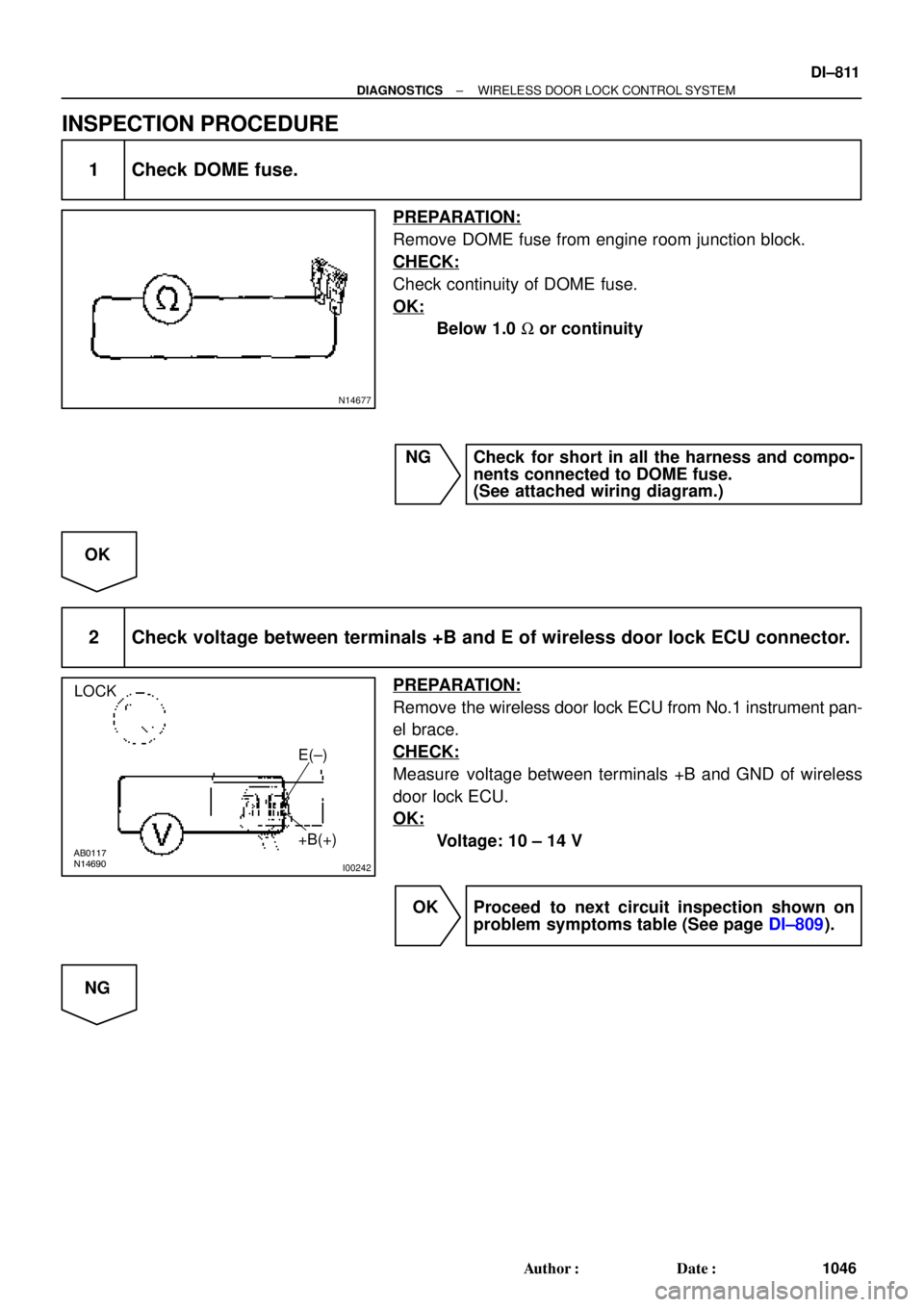
AB0117
N14690
I00242
LOCK
E(±)
+B(+)
± DIAGNOSTICSWIRELESS DOOR LOCK CONTROL SYSTEM
DI±811
1046 Author�: Date�:
INSPECTION PROCEDURE
1 Check DOME fuse.
PREPARATION:
Remove DOME fuse from engine room junction block.
CHECK:
Check continuity of DOME fuse.
OK:
Below 1.0 W or continuity
NG Check for short in all the harness and compo-
nents connected to DOME fuse.
(See attached wiring diagram.)
OK
2 Check voltage between terminals +B and E of wireless door lock ECU connector.
PREPARATION:
Remove the wireless door lock ECU from No.1 instrument pan-
el brace.
CHECK:
Measure voltage between terminals +B and GND of wireless
door lock ECU.
OK:
Voltage: 10 ± 14 V
OK Proceed to next circuit inspection shown on
problem symptoms table (See page DI±809).
NG