Page 5 of 4592
 Moisture present in refrig")
I01387
Condition : Periodically cools and then fails to cool
I01388
Condition: Insufficient cooling
± AIR CONDITIONINGAIR CONDITIONING SYSTEM
AC±5
2487 Author�: Date�:
(2) Moisture present in refrigeration system.
Symptom seen in
refrigeration systemProbable causeDiagnosisRemedy
During operation, pressure on low
pressure side sometimes become
a vacuum and sometime normal
Moisture entered in refrigeration
system freezes at expansion valve
orifice and temporarily stops cycle,
but normal state is restored after a
time when the ice melts� Drier oversaturated state
� Moisture in refrigeration system
freezes at expansion valve orifice
and blocks circulation of refriger-
ant(1) Replace receiver
(2) Remove moisture in cycle
through repeatedly evacuating air
(3) Charge proper amount of new
refrigerant
(3) Insufficient cooling
Symptom seen in
refrigeration systemProbable causeDiagnosisRemedy
� Pressure low on both low and
high pressure sides
� Bubbles seen in sight glass con-
tinuously
� Insufficient cooling performance
Gas leakage at some place in re-
frigeration system� Insufficient refrigerant in system
� Refrigerant leaking
(1) Check for gas leakage with gas
leak detector and repair if neces-
sary
(2) Charge proper amount of re-
frigerant
(3) If indicated pressure value is
near 0 when connected to gauge,
create the vacuum after inspecting
and repairing the location of the
leak
Page 13 of 4592
AC0LL±02
Z19146
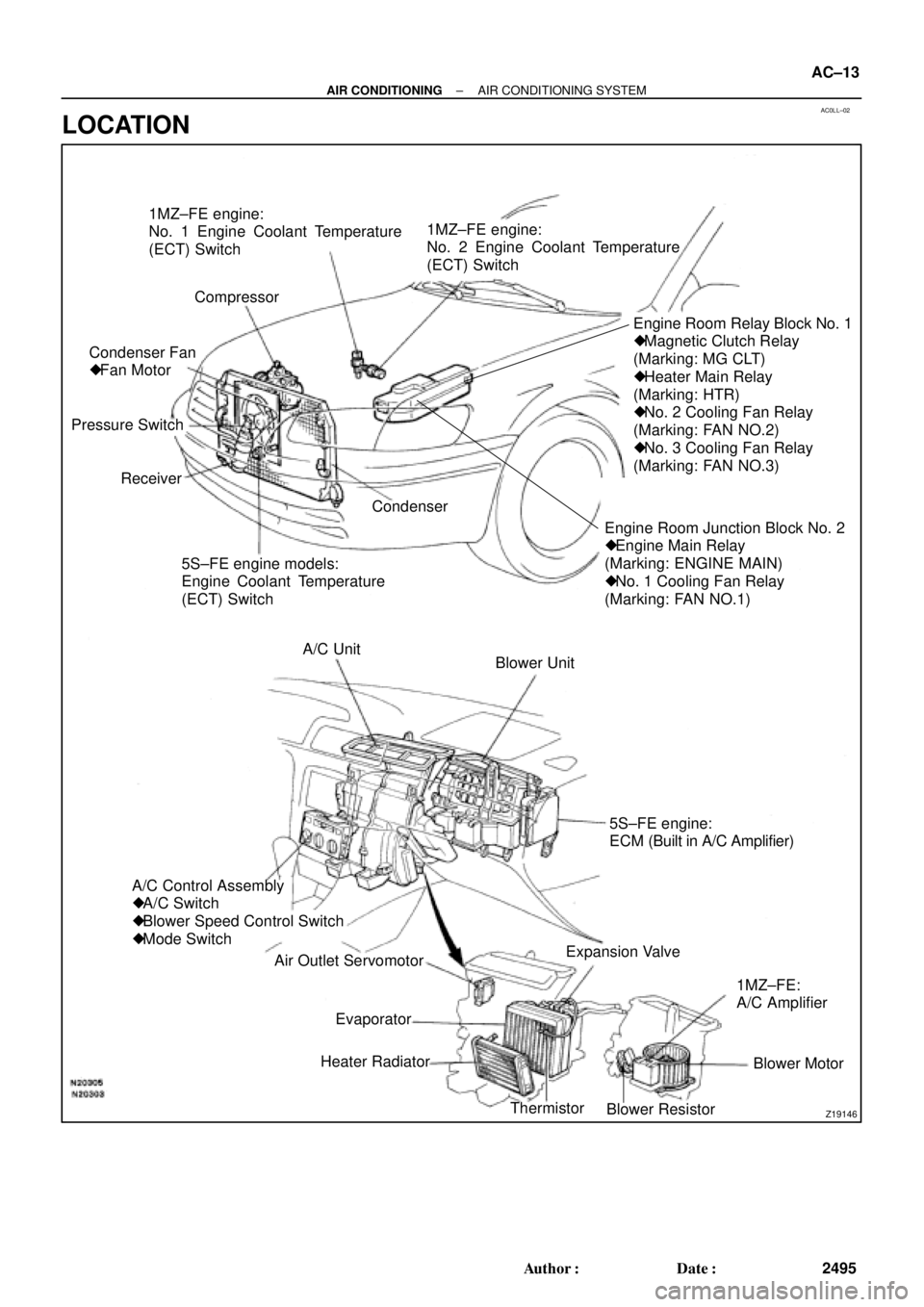
1MZ±FE engine:
No. 1 Engine Coolant Temperature
(ECT) Switch
Compressor
Engine Room Junction Block No. 2
� Engine Main Relay
(Marking: ENGINE MAIN)
� No. 1 Cooling Fan Relay
(Marking: FAN NO.1)Engine Room Relay Block No. 1
� Magnetic Clutch Relay
(Marking: MG CLT)
� Heater Main Relay
(Marking: HTR)
� No. 2 Cooling Fan Relay
(Marking: FAN NO.2)
� No. 3 Cooling Fan Relay
(Marking: FAN NO.3)
5S±FE engine models:
Engine Coolant Temperature
(ECT) Switch Receiver Pressure SwitchCondenser Fan
� Fan Motor1MZ±FE engine:
No. 2 Engine Coolant Temperature
(ECT) Switch
Condenser
Blower Unit A/C Unit
A/C Control Assembly
� A/C Switch
� Blower Speed Control Switch
� Mode Switch
Air Outlet Servomotor
Heater Radiator
Thermistor
Blower ResistorBlower Motor 1MZ±FE:
A/C Amplifier Expansion Valve5S±FE engine:
ECM (Built in A/C Amplifier)
Evaporator
± AIR CONDITIONINGAIR CONDITIONING SYSTEM
AC±13
2495 Author�: Date�:
LOCATION
Page 14 of 4592

AC21T±01
AC±14
± AIR CONDITIONINGTROUBLESHOOTING
2496 Author�: Date�:
TROUBLESHOOTING
PROBLEM SYMPTOMS TABLE
Use the table below to help you find the cause of the problem. The numbers indicate the priority of the likely
cause of the problem. Check each part in order. If necessary, replace these parts.
SymptomSuspect AreaSee page
No blower operation
4. HTR Fuse
5. Heater main relay
6. Blower motor
7. Blower resistor
8. Blower speed control switch
9. Wire harness±
AC±70
AC±63
AC±64
AC±84
±
No air temperature control1. Engine coolant volume
2. A/C control assembly±
AC±80
No air inlet control1. A/C control assemblyAC±80
No air outlet control
1. HTR Fuse
2. Air outlet servomotor
3. Mode switch±
AC±65
AC±84
No compressor operation
1. Refrigerant volume
2. A.C Fuse
3. HTR Fuse
4. Magnetic clutch relay
5. Magnetic clutch
6. Compressor
7. Pressure switch
8. Heater main relay
9. Blower speed control switch
10.A/C switch
11. *1 ECM
*
2 A/C amplifier
12.Wire harness
AC±3
±
±
AC±71
AC±39
AC±39
AC±67
AC±70
AC±84
AC±84
DI±218
AC±88
±
No compressor operates intermittently
1. Refrigerant volume
2. Condenser fan
3. Pressure switch
4. *1 ECM
*2 A/C amplifier
5. Thermistor
6. Wire harnessAC±3
AC±74
AC±67
DI±218
AC±88
AC±24
±
No cool air comes out
1. Refrigerant volume
2. Refrigerant pressure
3. Drive belt
4. Compressor lock sensor
5. Magnetic clutch
6. Compressor
7. Pressure switch
8. Thermistor
9. A/C switch
10.*1 ECM
*2 A/C amplifier
11. Wire harnessAC±3
AC±3
AC±16
AC±16
AC±39
AC±39
AC±67
AC±24
AC±84
DI±218
AC±88
±
Page 17 of 4592
AC0LN±02
Z19189
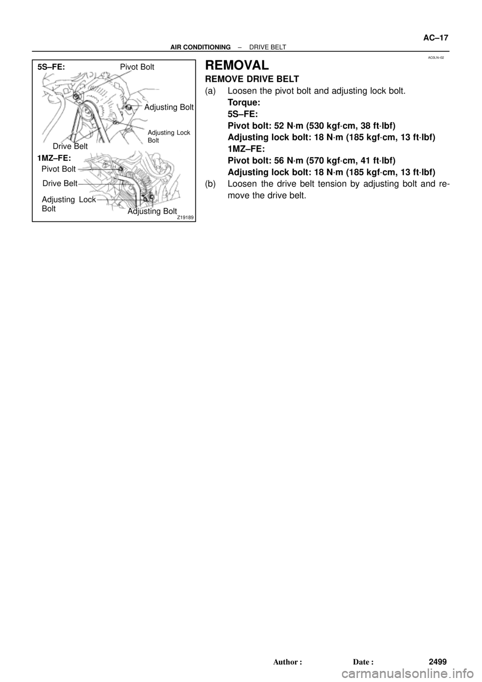
Pivot Bolt
Adjusting Bolt
Drive Belt
Pivot Bolt
Drive Belt
Adjusting Lock
Bolt
Adjusting Bolt 5S±FE:
1MZ±FE:
Adjusting Lock
Bolt
± AIR CONDITIONINGDRIVE BELT
AC±17
2499 Author�: Date�:
REMOVAL
REMOVE DRIVE BELT
(a) Loosen the pivot bolt and adjusting lock bolt.
Torque:
5S±FE:
Pivot bolt: 52 N´m (530 kgf´cm, 38 ft´lbf)
Adjusting lock bolt: 18 N´m (185 kgf´cm, 13 ft´lbf)
1MZ±FE:
Pivot bolt: 56 N´m (570 kgf´cm, 41 ft´lbf)
Adjusting lock bolt: 18 N´m (185 kgf´cm, 13 ft´lbf)
(b) Loosen the drive belt tension by adjusting bolt and re-
move the drive belt.
Page 19 of 4592
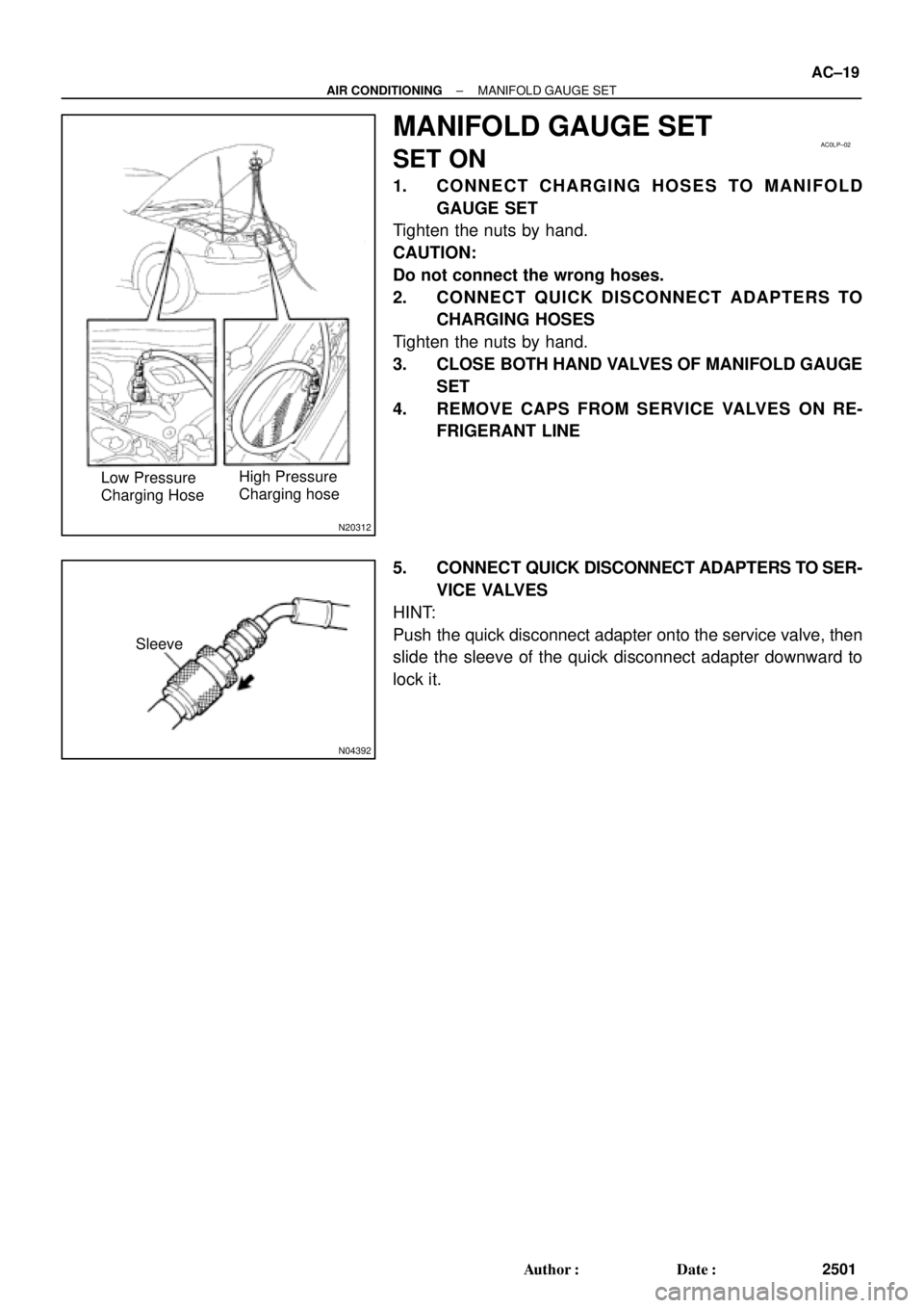
N20312
High Pressure
Charging hose Low Pressure
Charging Hose
AC0LP±02
N04392
Sleeve
± AIR CONDITIONINGMANIFOLD GAUGE SET
AC±19
2501 Author�: Date�:
MANIFOLD GAUGE SET
SET ON
1. CONNECT CHARGING HOSES TO MANIFOLD
GAUGE SET
Tighten the nuts by hand.
CAUTION:
Do not connect the wrong hoses.
2. CONNECT QUICK DISCONNECT ADAPTERS TO
CHARGING HOSES
Tighten the nuts by hand.
3. CLOSE BOTH HAND VALVES OF MANIFOLD GAUGE
SET
4. REMOVE CAPS FROM SERVICE VALVES ON RE-
FRIGERANT LINE
5. CONNECT QUICK DISCONNECT ADAPTERS TO SER-
VICE VALVES
HINT:
Push the quick disconnect adapter onto the service valve, then
slide the sleeve of the quick disconnect adapter downward to
lock it.
Page 20 of 4592
AC0LQ±02
N06553
AC±20
± AIR CONDITIONINGMANIFOLD GAUGE SET
2502 Author�: Date�:
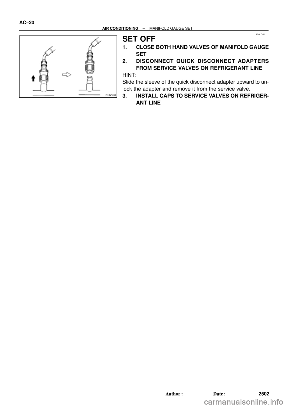
SET OFF
1. CLOSE BOTH HAND VALVES OF MANIFOLD GAUGE
SET
2. DISCONNECT QUICK DISCONNECT ADAPTERS
FROM SERVICE VALVES ON REFRIGERANT LINE
HINT:
Slide the sleeve of the quick disconnect adapter upward to un-
lock the adapter and remove it from the service valve.
3. INSTALL CAPS TO SERVICE VALVES ON REFRIGER-
ANT LINE
Page 23 of 4592
AC0LT±03
± AIR CONDITIONINGREFRIGERANT LINE
AC±23
2505 Author�: Date�:
REPLACEMENT
1. DISCHARGE REFRIGERANT FROM REFRIGERATION SYSTEM
2. REPLACE FAULTY TUBE OR HOSE
NOTICE:
Cap the open fittings immediately to keep moisture or dirt out of the system.
3. TIGHTEN JOINT OF BOLT OR NUT TO SPECIFIED TORQUE
NOTICE:
Connections should not be torqued tighter than the specified torque.
Part tightenedN´mkgf´cmft´lbf
Receiver x Liquid tube5.45548 in.´lbf
Condenser x Discharge hose101007
Condenser x Liquid tube1414010
Compressor x Discharge hose101007
Compressor x Suction hose101007
Expansion valve x Evaporator5.45548 in.´lbf
Suction line (Piping joint)3233024
Suction line (Block joint)101007
4. EVACUATE AIR FROM REFRIGERATION SYSTEM AND CHARGE WITH REFRIGERANT
Specified amount : 800 ± 50g (28.22 ± 1.76 oz.)
5. INSPECT FOR LEAKAGE OF REFRIGERANT
Using a gas leak detector, check for leakage of refrigerant.
6. INSPECT AIR CONDITIONING OPERATION
Page 28 of 4592

I03838
SST
I03839
PushSST
Pull
SST
Release
Lever
I06919
Disconnect the tube
using hand
Screw
Driver
Tube
I06878
Correct Wrong
Gap
N20281
AC±28
± AIR CONDITIONINGAIR CONDITIONING UNIT
2510 Author�: Date�:
(1) Inert SST to piping clamp.
HINT:
Confirm the direction of the piping clamp claw and SST using
the illustration showing on the caution label.
(2) Push down SST and release the clamp lock.
NOTICE:
Be careful not to deform the tubes, when pushing SST.
(3) Pull SST slightly and push the release lever, then re-
move the piping clamp with SST.
(4) Remove the piping clamp from SST.
(b) Disconnect the both tubes.
NOTICE:
�Do not use tools like screwdriver to remove the tube.
�Cap the open fittings immediately to keep moisture or
dirt out of the system.
HINT:
At the time of installation, please refer to the following item.
�Lubricate 4 new O±rings with compressor oil and install
the tubes.
�After connection, check the fitting for claw of the piping
clamp.
7. REMOVE A/C UNIT
(a) Disconnect the connector.
(b) Slide the floor carpet backward.
(c) Remove the rear heater duct.
(d) Remove the 2 nuts and A/C unit.