Page 1144 of 4592
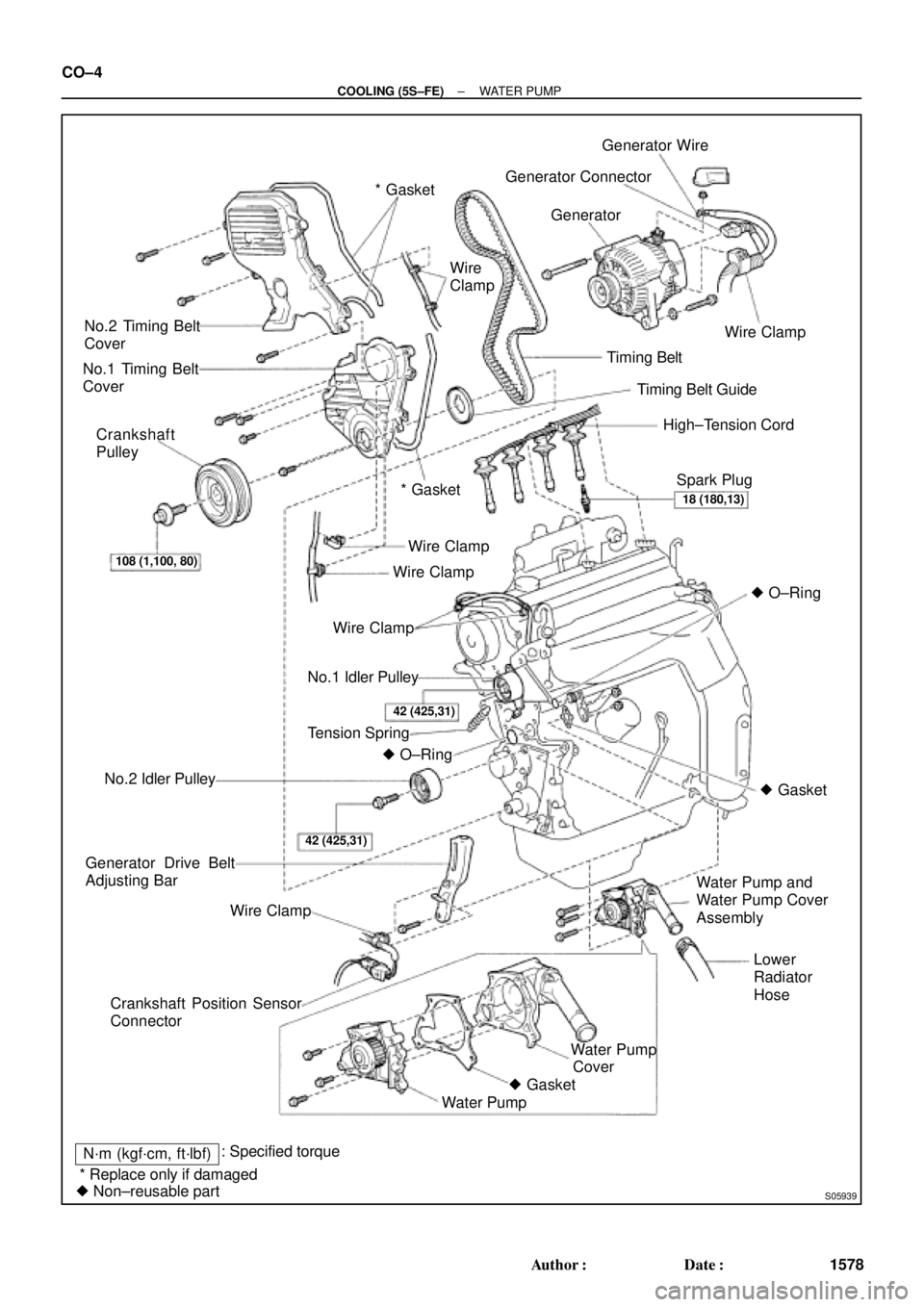
S05939
No.2 Timing Belt
Cover
No.1 Timing Belt
Cover
Crankshaft
Pulley
No.2 Idler Pulley
Generator Drive Belt
Adjusting Bar
Wire Clamp
Crankshaft Position Sensor
Connector* Gasket
No.1 Idler Pulley
Tension Spring
� O±Ring
Water PumpWater PumpTiming Belt
Timing Belt Guide
Lower
Radiator
Hose Water Pump and
Water Pump Cover
Assembly High±Tension Cord Generator Wire
� Gasket Wire Clamp
Wire Clamp
Wire ClampWire Clamp Wire
Clamp
* GasketGenerator Connector
Generator
Spark Plug
� O±Ring
� Gasket
N´m (kgf´cm, ft´lbf): Specified torque
� Non±reusable part
108 (1,100, 80)18 (180,13)
42 (425,31)
42 (425,31)
* Replace only if damagedCover CO±4
± COOLING (5S±FE)WATER PUMP
1578 Author�: Date�:
Page 1225 of 4592
A00359
± DIAGNOSTICSENGINE (5S±FE)
DI±13
248 Author�: Date�:
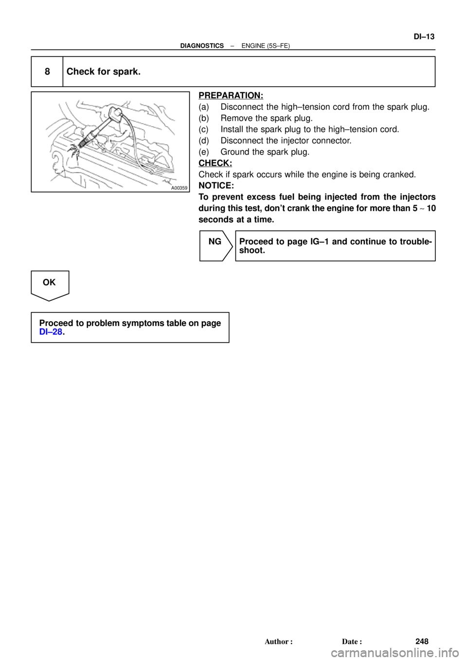
8 Check for spark.
PREPARATION:
(a) Disconnect the high±tension cord from the spark plug.
(b) Remove the spark plug.
(c) Install the spark plug to the high±tension cord.
(d) Disconnect the injector connector.
(e) Ground the spark plug.
CHECK:
Check if spark occurs while the engine is being cranked.
NOTICE:
To prevent excess fuel being injected from the injectors
during this test, don't crank the engine for more than 5 ~ 10
seconds at a time.
NG Proceed to page IG±1 and continue to trouble-
shoot.
OK
Proceed to problem symptoms table on page
DI±28.
Page 1305 of 4592
A00434
± DIAGNOSTICSENGINE (5S±FE)
DI±93
328 Author�: Date�:
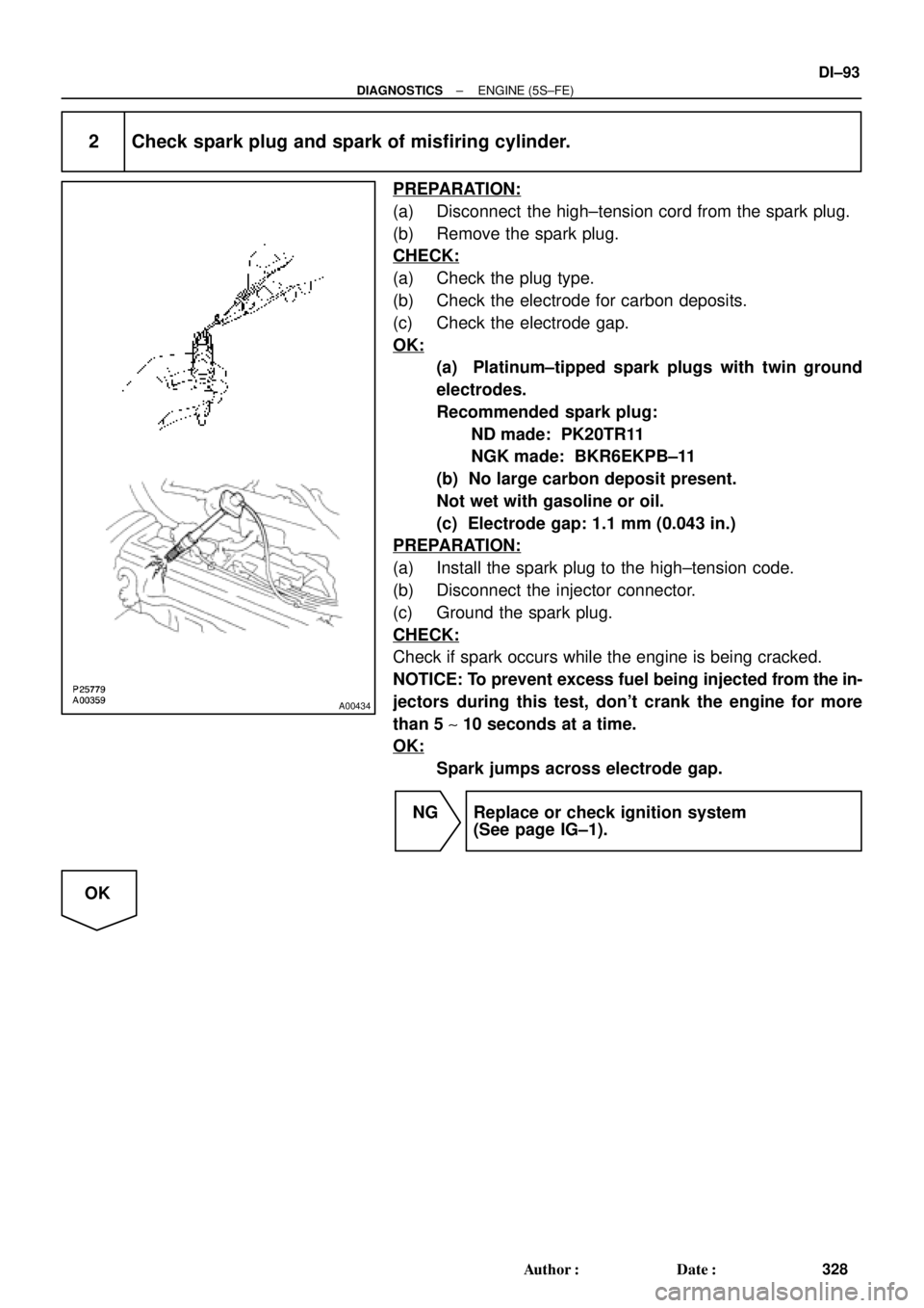
2 Check spark plug and spark of misfiring cylinder.
PREPARATION:
(a) Disconnect the high±tension cord from the spark plug.
(b) Remove the spark plug.
CHECK:
(a) Check the plug type.
(b) Check the electrode for carbon deposits.
(c) Check the electrode gap.
OK:
(a) Platinum±tipped spark plugs with twin ground
electrodes.
Recommended spark plug:
ND made: PK20TR11
NGK made: BKR6EKPB±11
(b) No large carbon deposit present.
Not wet with gasoline or oil.
(c) Electrode gap: 1.1 mm (0.043 in.)
PREPARATION:
(a) Install the spark plug to the high±tension code.
(b) Disconnect the injector connector.
(c) Ground the spark plug.
CHECK:
Check if spark occurs while the engine is being cracked.
NOTICE: To prevent excess fuel being injected from the in-
jectors during this test, don't crank the engine for more
than 5 ~ 10 seconds at a time.
OK:
Spark jumps across electrode gap.
NG Replace or check ignition system
(See page IG±1).
OK
Page 1375 of 4592

± DIAGNOSTICSENGINE (5S±FE)
DI±163
398 Author�: Date�:
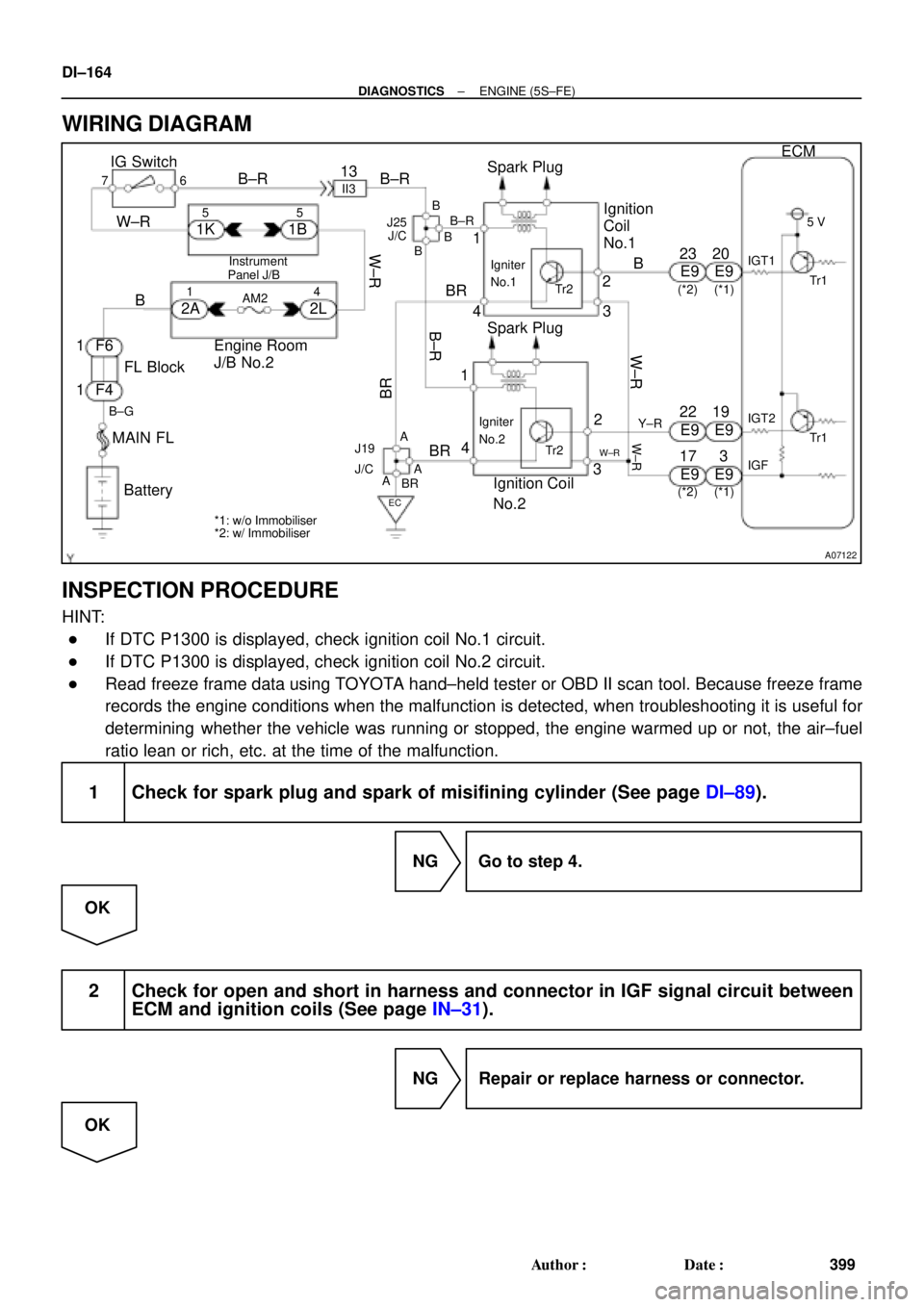
DTC P1300 Igniter Circuit Malfunction No.1
DTC P1310 Igniter Circuit Malfunction No.2
CIRCUIT DESCRIPTION
The ECM determines the ignition timing, turns on Tr1 at a predetermined angle (°CA) before the desired
ignition timing and outputs and ignition signal (IGT) 1 to the igniter.
Since the width of the IGT signal is constant, the dwell angle control circuit in the igniter determines the time
the control circuit starts primary current flow to the ignition coil based on the engine rpm and ignition timing
one revolution ago, that is, the time the Tr2 turns on.
When it reaches the ignition timing, the ECM turns Tr1 off and outputs the IGT signal O.
This turns Tr2 off, interrupting the primary current flow and generating a high voltage in the secondary coil
which causes the spark plug to spark. Also, by the counter electromotive force generated when the primary
current is interrupted, the igniter sends an ignition confirmation signal (IGF) to the ECM. The ECM stops fuel
injection as a fail safe function when the IGF signal is not input to the ECM.
DTC No.DTC Detecting ConditionTrouble Area
P1300No IGF signal to ECM for 4 consecutive IGT1 signals during
engine running�Open or short in IGF or IGT circuit from igniter to ECM
�Ignition coil No.1 (Igniter No.1)
�ECM
P1310No IGF signal to ECM for 4 consecutive IGT2 signals during
engine running�Open or short in IGF or IGT circuit from igniter to ECM
�Ignition coil No.2 (Igniter No.2)
�ECM
HINT:
Ignition coil No.1 is for cylinder No.1 and No.4, and ignition coil No.2 is for cylinder No.2 and No.3.
DI01G±06
Page 1376 of 4592
A07122
IG Switch
B±R
BatteryEngine Room
J/B No.2
76B±R13
1II3B±R
B
BR
Spark Plug
Spark Plug
2
3 2
3 4
Tr2 Igniter
No.1
Ignition
Coil
No.1
FL Block
Y±R
BR
B
20
19
IGT2
Tr1
E9
E9
E9
W±R
IGT1
IGF5 V
Tr1
Ignition Coil
No.2
Igniter
No.2
AA A
EC
Tr2
W±R
B±R 5 51B 1K
Instrument
W±R
W±R
2L 2A
4 1
AM2B
F4 F6 1
1
B±G
MAIN FL
3 1
4
J/C J25
*1: w/o Immobiliser
*2: w/ Immobiliser(*1) (*2)
ECM
E9 23
E9 22
E9 17
(*1) (*2)
W±R
Panel J/BB
B
BR
BR J19
J/C
DI±164
± DIAGNOSTICSENGINE (5S±FE)
399 Author�: Date�:
WIRING DIAGRAM
INSPECTION PROCEDURE
HINT:
�If DTC P1300 is displayed, check ignition coil No.1 circuit.
�If DTC P1300 is displayed, check ignition coil No.2 circuit.
�Read freeze frame data using TOYOTA hand±held tester or OBD II scan tool. Because freeze frame
records the engine conditions when the malfunction is detected, when troubleshooting it is useful for
determining whether the vehicle was running or stopped, the engine warmed up or not, the air±fuel
ratio lean or rich, etc. at the time of the malfunction.
1 Check for spark plug and spark of misifining cylinder (See page DI±89).
NG Go to step 4.
OK
2 Check for open and short in harness and connector in IGF signal circuit between
ECM and ignition coils (See page IN±31).
NG Repair or replace harness or connector.
OK
Page 1418 of 4592
P23917
DI±206
± DIAGNOSTICSENGINE (1MZ±FE)
441 Author�: Date�:
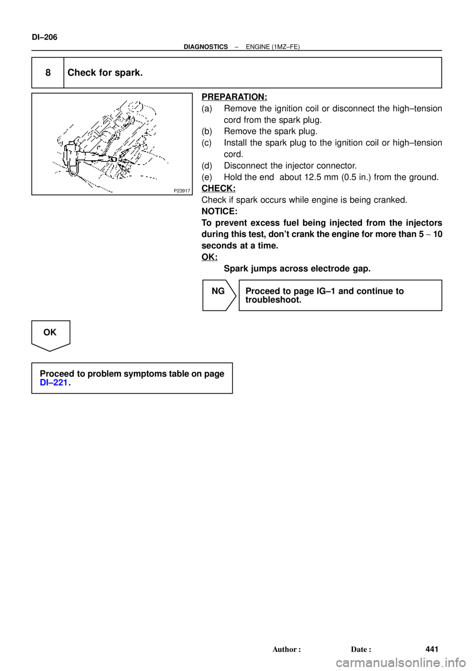
8 Check for spark.
PREPARATION:
(a) Remove the ignition coil or disconnect the high±tension
cord from the spark plug.
(b) Remove the spark plug.
(c) Install the spark plug to the ignition coil or high±tension
cord.
(d) Disconnect the injector connector.
(e) Hold the end about 12.5 mm (0.5 in.) from the ground.
CHECK:
Check if spark occurs while engine is being cranked.
NOTICE:
To prevent excess fuel being injected from the injectors
during this test, don't crank the engine for more than 5 ~ 10
seconds at a time.
OK:
Spark jumps across electrode gap.
NG Proceed to page IG±1 and continue to
troubleshoot.
OK
Proceed to problem symptoms table on page
DI±221.
Page 1491 of 4592
A00221P25779
P23917
± DIAGNOSTICSENGINE (1MZ±FE)
DI±279
514 Author�: Date�:
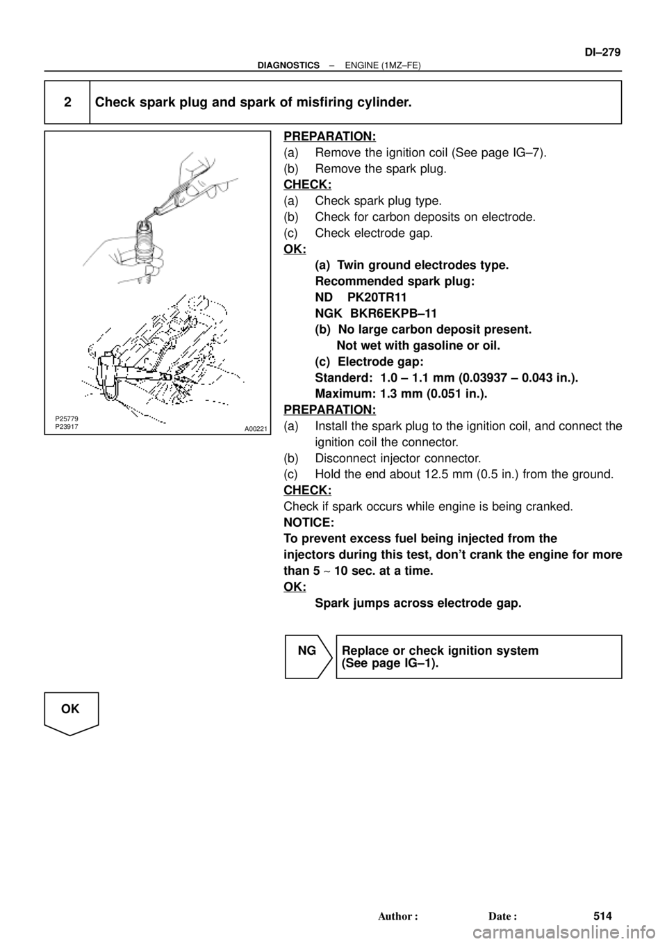
2 Check spark plug and spark of misfiring cylinder.
PREPARATION:
(a) Remove the ignition coil (See page IG±7).
(b) Remove the spark plug.
CHECK:
(a) Check spark plug type.
(b) Check for carbon deposits on electrode.
(c) Check electrode gap.
OK:
(a) Twin ground electrodes type.
Recommended spark plug:
ND PK20TR11
NGK BKR6EKPB±11
(b) No large carbon deposit present.
Not wet with gasoline or oil.
(c) Electrode gap:
Standerd: 1.0 ± 1.1 mm (0.03937 ± 0.043 in.).
Maximum: 1.3 mm (0.051 in.).
PREPARATION:
(a) Install the spark plug to the ignition coil, and connect the
ignition coil the connector.
(b) Disconnect injector connector.
(c) Hold the end about 12.5 mm (0.5 in.) from the ground.
CHECK:
Check if spark occurs while engine is being cranked.
NOTICE:
To prevent excess fuel being injected from the
injectors during this test, don't crank the engine for more
than 5 ~ 10 sec. at a time.
OK:
Spark jumps across electrode gap.
NG Replace or check ignition system
(See page IG±1).
OK
Page 1563 of 4592

S00251
From BatteryIgnition Coil
Spark Plug
IGC1
IGC2
IGC3
GND TA C IGT1
IGT2
IGT3
IGF
To Tachometer ECM G
NE
Camshaft
Position
Sensor
Crankshaft
Position
Sensor
Various
SensorNo.2 Cylinder
No.1 Cylinder
No.4 Cylinder
No.3 Cylinder
No.6 Cylinder
No.5 Cylinder
± DIAGNOSTICSENGINE (1MZ±FE)
DI±351
586 Author�: Date�:
DTC P1300 Igniter Circuit Malfunction
CIRCUIT DESCRIPTION
A DIS (Direct Ignition System) has been adopted. The DIS improves the ignition timing accuracy, reduces
high±voltage loss, and enhances the overall reliability of the ignition system by eliminating the distributor.
The DIS is a 2±cylinder simultaneous ignition system which ignites 2 cylinders simultaneously with one igni-
tion coil. In the 2±cylinder simultaneous ignition system, each of the 2 spark plugs is connected to the end
of the secondary winding. High voltage generated in the secondary winding is applied directly to the spark
plugs. The sparks of the 2 spark plugs pass simultaneously from the center electrode to the ground elec-
trode.
The ECM determines ignition timing and outputs the ignition signals (IGT) for each cylinder. Based on IGT
signals, the igniter controls the primary ignition signals (IGC) for all ignition coils. At the same time, the igniter
also sends an ignition confirmation signal (IGF) as a fail±safe measure to the ECM.
DTC No.DTC Detecting ConditionTrouble Area
P1300
Condition (a) is repeated 3 times consecutively during 6
consecutively IGT signals while engine is running
(a) IGF signal is not input to ECM for 2 or more ignitions�Open or short in IGF or IGT circuit from igniter to ECM
�Igniter
�ECM
DI084±06