Page 2839 of 4592

IN04Q±03
IN±36
± INTRODUCTIONTERMS
36 Author�: Date�:
TERMS
ABBREVIATIONS USED IN THIS MANUAL
AbbreviationsMeaning
ABSAnti±Lock Brake System
ACAlternating Current
ACCAccessory
ACISAcoustic Control Induction System
ACSDAutomatic Cold Start Device
A.D.D.Automatic Disconnecting Differential
A/FAir±Fuel Ratio
AHCActive Height Control Suspension
ALRAutomatic Locking Retractor
ALTAlternator
AMPAmplifier
ANTAntenna
APPROX.Approximately
A/TAutomatic Transmission (Transaxle)
AT FAutomatic Transmission Fluid
AUTOAutomatic
AUXAuxiliary
AV GAverage
AV SAdaptive Variable Suspension
BACSBoost Altitude Compensation System
BATBattery
BDCBottom Dead Center
B/LBi±Level
B/SBore±Stroke Ratio
BTDCBefore Top Dead Center
BVSVBimetallic Vacuum Switching Valve
Calif.California
CBCircuit Breaker
CCoCatalytic Converter For Oxidation
CDCompact Disc
CFCornering Force
CGCenter Of Gravity
CHChannel
COMB.Combination
CPECoupe
CPSCombustion Pressure Sensor
CPUCentral Processing Unit
CRSChild Restraint System
CTRCenter
C/VCheck Valve
CVControl Valve
CWCurb Weight
Page 2841 of 4592

IN±38
± INTRODUCTIONTERMS
38 Author�: Date�:
HIDHigh Intensity Discharge (Head Lamp)
HSGHousing
HTHard Top
HWSHeated Windshield System
IACIdle Air Control
ICIntegrated circuit
IDIIndirect Diesel Injection
IFSIndependent Front Suspension
IGIgnition
IIAIntegrated Ignition Assembly
INIntake (Manifold, Valve)
INTIntermittent
I/PInstrument Panel
IRSIndependent Rear Suspension
J/BJunction Block
J/CJunction Connector
KDKick±Down
LANLocal Area Network
LBLiftback
LCDLiquid Crystal Display
LEDLight Emitting Diode
LHLeft±Hand
LHDLeft±Hand Drive
L/H/WLength, Height, Width
LLCLong±Life Coolant
LNGLiquified Natural Gas
LOLow
LPGLiquified Petroleum Gas
LSDLimited Slip Differential
LSP & PVLoad Sensing Proportioning And Bypass Valve
LSPVLoad Sensing Proportioning Valve
MAX.Maximum
MICMicrophone
MILMalfunction Indicator Lamp
MIN.Minimum
MPMultipurpose
MPXMultiplex Communication System
M/TManual Transmission
MTMount
MTGMounting
NNeutral
NANatural Aspiration
No.Number
O/DOverdrive
OEMOriginal Equipment Manufacturing
OHCOverhead Camshaft
Page 2880 of 4592

IN04Q±03
IN±34
± INTRODUCTIONTERMS
34 Author�: Date�:
TERMS
ABBREVIATIONS USED IN THIS MANUAL
AbbreviationsMeaning
ABSAnti±Lock Brake System
ACAlternating Current
ACCAccessory
ACISAcoustic Control Induction System
ACSDAutomatic Cold Start Device
A.D.D.Automatic Disconnecting Differential
A/FAir±Fuel Ratio
AHCActive Height Control Suspension
ALRAutomatic Locking Retractor
ALTAlternator
AMPAmplifier
ANTAntenna
APPROX.Approximately
A/TAutomatic Transmission (Transaxle)
AT FAutomatic Transmission Fluid
AUTOAutomatic
AUXAuxiliary
AV GAverage
AV SAdaptive Variable Suspension
BACSBoost Altitude Compensation System
BATBattery
BDCBottom Dead Center
B/LBi±Level
B/SBore±Stroke Ratio
BTDCBefore Top Dead Center
BVSVBimetallic Vacuum Switching Valve
Calif.California
CBCircuit Breaker
CCoCatalytic Converter For Oxidation
CDCompact Disc
CFCornering Force
CGCenter Of Gravity
CHChannel
COMB.Combination
CPECoupe
CPSCombustion Pressure Sensor
CPUCentral Processing Unit
CRSChild Restraint System
CTRCenter
C/VCheck Valve
CVControl Valve
CWCurb Weight
Page 2882 of 4592

IN±36
± INTRODUCTIONTERMS
36 Author�: Date�:
HIDHigh Intensity Discharge (Head Lamp)
HSGHousing
HTHard Top
HWSHeated Windshield System
IACIdle Air Control
ICIntegrated circuit
IDIIndirect Diesel Injection
IFSIndependent Front Suspension
IGIgnition
IIAIntegrated Ignition Assembly
INIntake (Manifold, Valve)
INTIntermittent
I/PInstrument Panel
IRSIndependent Rear Suspension
J/BJunction Block
J/CJunction Connector
KDKick±Down
LANLocal Area Network
LBLiftback
LCDLiquid Crystal Display
LEDLight Emitting Diode
LHLeft±Hand
LHDLeft±Hand Drive
L/H/WLength, Height, Width
LLCLong±Life Coolant
LNGLiquified Natural Gas
LOLow
LPGLiquified Petroleum Gas
LSDLimited Slip Differential
LSP & PVLoad Sensing Proportioning And Bypass Valve
LSPVLoad Sensing Proportioning Valve
MAX.Maximum
MICMicrophone
MILMalfunction Indicator Lamp
MIN.Minimum
MPMultipurpose
MPXMultiplex Communication System
M/TManual Transmission
MTMount
MTGMounting
NNeutral
NANatural Aspiration
No.Number
O/DOverdrive
OEMOriginal Equipment Manufacturing
OHCOverhead Camshaft
Page 2936 of 4592

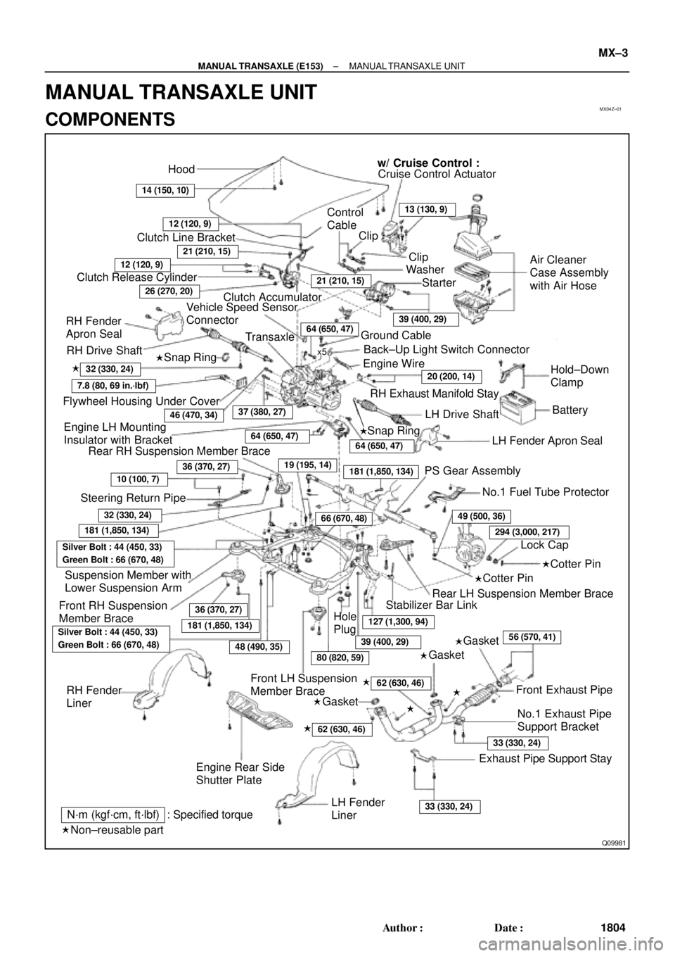
MX04Z±01
Q09981
Hood
14 (150, 10)
w/ Cruise Control :
Cruise Control Actuator
12 (120, 9)
Clutch Line Bracket
21 (210, 15)
12 (120, 9)
Clutch Release Cylinder
26 (270, 20)
RH Drive Shaft�
�32 (330, 24)
7.8 (80, 69 in.´lbf)
Flywheel Housing Under CoverRH Fender
Apron SealClutch Accumulator
Vehicle Speed Sensor
Connector
46 (470, 34)
Engine LH Mounting
Insulator with Bracket
Rear RH Suspension Member Brace
37 (380, 27)
Transaxle
64 (650, 47)
36 (370, 27)
10 (100, 7)
Steering Return Pipe
19 (195, 14)
32 (330, 24)
181 (1,850, 134)
Silver Bolt : 44 (450, 33)
Green Bolt : 66 (670, 48)
Suspension Member with
Lower Suspension Arm
Front RH Suspension
Member Brace
181 (1,850, 134)
Control
Cable
Clip13 (130, 9)
Clip
Washer
Starter
21 (210, 15)
39 (400, 29)
Air Cleaner
Case Assembly
with Air Hose
64 (650, 47)Ground Cable
x5Back±Up Light Switch Connector
Engine Wire
20 (200, 14)Hold±Down
Clamp
Battery
LH Drive Shaft
LH Fender Apron Seal RH Exhaust Manifold Stay
64 (650, 47)
181 (1,850, 134)PS Gear Assembly
No.1 Fuel Tube Protector
49 (500, 36)
294 (3,000, 217)
Lock Cap
Rear LH Suspension Member Brace
Stabilizer Bar Link
Hole
Plug
127 (1,300, 94)
39 (400, 29)
80 (820, 59)48 (490, 35)
Silver Bolt : 44 (450, 33)
Green Bolt : 66 (670, 48)
Front LH Suspension
Member Brace RH Fender
Liner
Engine Rear Side
Shutter Plate
56 (570, 41)
�
�
62 (630, 46) �
62 (630, 46) �
Front Exhaust Pipe
No.1 Exhaust Pipe
Support Bracket
33 (330, 24)
Exhaust Pipe Support Stay
33 (330, 24)LH Fender
Liner
66 (670, 48)
Snap Ring
�Snap Ring
�Cotter Pin
�Cotter Pin
�Gasket
�Gasket
�Gasket
Non±reusable part: Specified torque
N´m (kgf´cm, ft´lbf)
�
36 (370, 27)
± MANUAL TRANSAXLE (E153)MANUAL TRANSAXLE UNIT
MX±3
1804 Author�: Date�:
MANUAL TRANSAXLE UNIT
COMPONENTS
Page 2985 of 4592

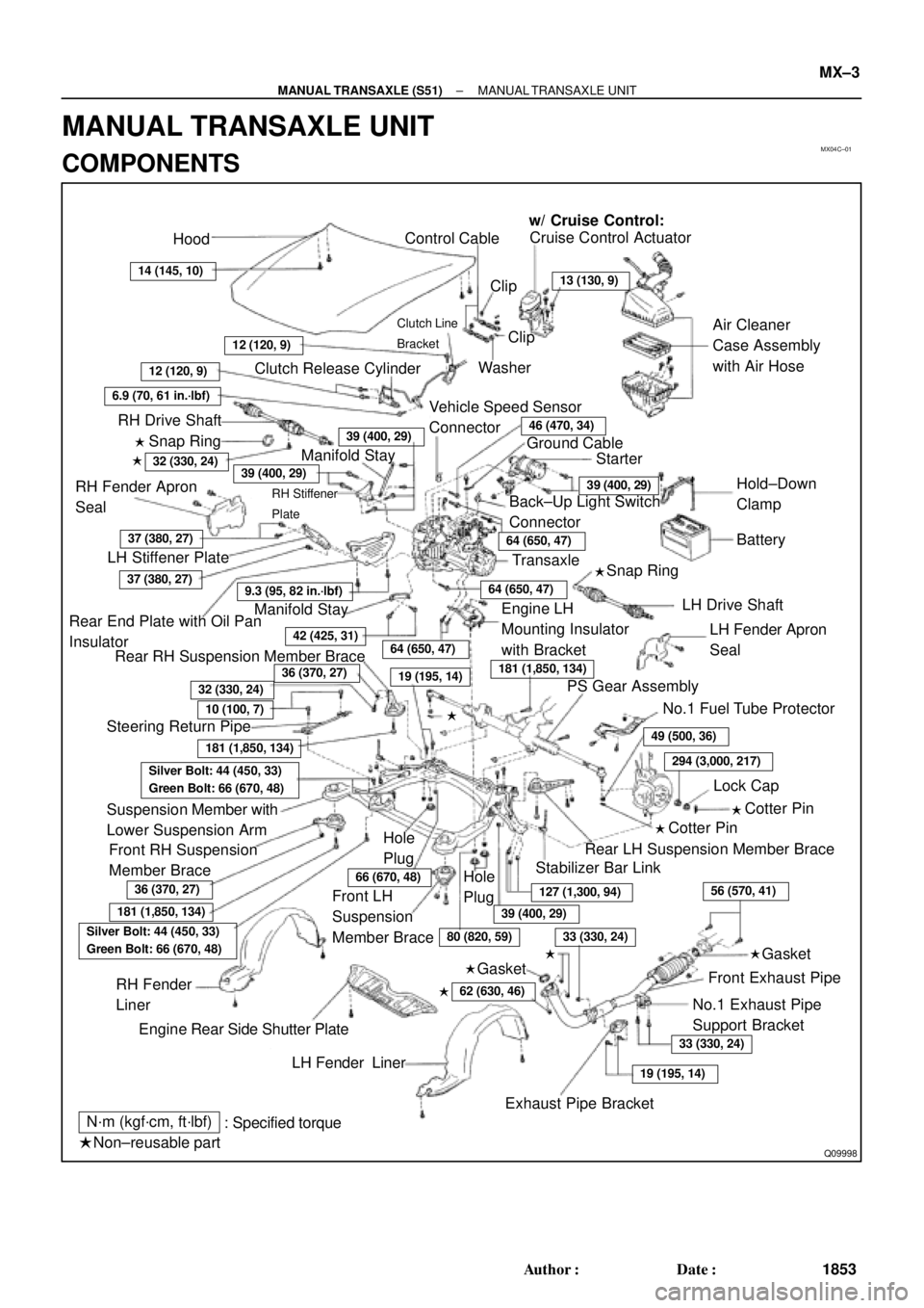
MX04C±01
Q09998
Hood
ClipCruise Control Actuator
Control Cable
Clutch Line
Bracket
Clutch Release CylinderWasher
RH Drive Shaft
Snap Ring
RH Stiffener
Plate
Ground Cable
Starter
Battery
Snap Ring
LH Drive Shaft�
RH Fender Apron
Seal
LH Stiffener Plate
Manifold StayTransaxle Back±Up Light Switch
Connector
Rear End Plate with Oil Pan
InsulatorAir Cleaner
Case Assembly
with Air Hose
Vehicle Speed Sensor
Connector
No.1 Fuel Tube Protector Engine LH
Mounting Insulator
with Bracket
Rear RH Suspension Member Brace
PS Gear Assembly
Lock Cap
Rear LH Suspension Member Brace Manifold StayClip
LH Fender Apron
Seal
Suspension Member with
Lower Suspension Arm
Front RH Suspension
Member BraceStabilizer Bar Link
Front Exhaust PipeCotter Pin
RH Fender
Liner
LH Fender Liner
Exhaust Pipe BracketNo.1 Exhaust Pipe
Support Bracket
: Specified torque
Non±reusable partGasket w/ Cruise Control:
�
�
�
Cotter Pin
�
Hole
Plug
�
�
Engine Rear Side Shutter PlateHold±Down
Clamp
Hole
Plug
12 (120, 9)
13 (130, 9)
46 (470, 34)
39 (400, 29)
6.9 (70, 61 in.´lbf)
14 (145, 10)
12 (120, 9)
39 (400, 29)
39 (400, 29)
64 (650, 47)
56 (570, 41)
37 (380, 27)
9.3 (95, 82 in.´lbf)
42 (425, 31)
32 (330, 24)
Silver Bolt: 44 (450, 33)
Green Bolt: 66 (670, 48)
62 (630, 46)
64 (650, 47)
64 (650, 47)
37 (380, 27)
181 (1,850, 134)
181 (1,850, 134)
181 (1,850, 134)
36 (370, 27)
10 (100, 7)
32 (330, 24)19 (195, 14)
49 (500, 36)
294 (3,000, 217)
Silver Bolt: 44 (450, 33)
Green Bolt: 66 (670, 48)
36 (370, 27)66 (670, 48)
39 (400, 29)
127 (1,300, 94)
33 (330, 24)
33 (330, 24)
19 (195, 14)
80 (820, 59)
Gasket�
�� �
Steering Return Pipe
Front LH
Suspension
Member Brace
N´m (kgf´cm, ft´lbf)
± MANUAL TRANSAXLE (S51)MANUAL TRANSAXLE UNIT
MX±3
1853 Author�: Date�:
MANUAL TRANSAXLE UNIT
COMPONENTS
Page 3508 of 4592

SR06C±01
SR±2
± STEERINGTROUBLESHOOTING
2097 Author�: Date�:
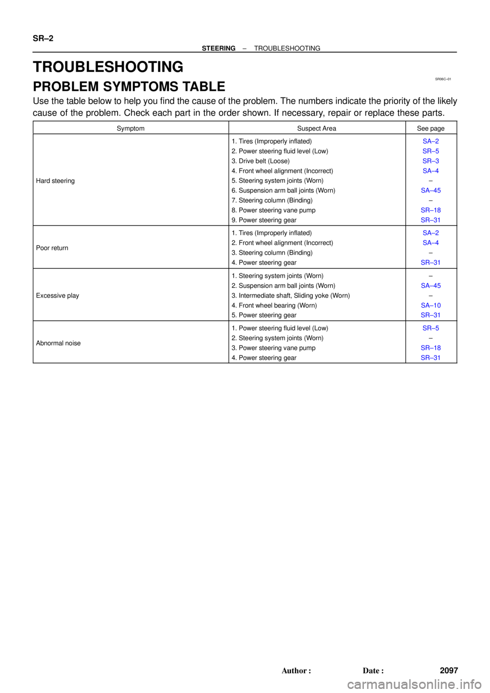
TROUBLESHOOTING
PROBLEM SYMPTOMS TABLE
Use the table below to help you find the cause of the problem. The numbers indicate the priority of the likely
cause of the problem. Check each part in the order shown. If necessary, repair or replace these parts.
SymptomSuspect AreaSee page
Hard steering
1. Tires (Improperly inflated)
2. Power steering fluid level (Low)
3. Drive belt (Loose)
4. Front wheel alignment (Incorrect)
5. Steering system joints (Worn)
6. Suspension arm ball joints (Worn)
7. Steering column (Binding)
8. Power steering vane pump
9. Power steering gearSA±2
SR±5
SR±3
SA±4
±
SA±45
±
SR±18
SR±31
Poor return
1. Tires (Improperly inflated)
2. Front wheel alignment (Incorrect)
3. Steering column (Binding)
4. Power steering gearSA±2
SA±4
±
SR±31
Excessive play
1. Steering system joints (Worn)
2. Suspension arm ball joints (Worn)
3. Intermediate shaft, Sliding yoke (Worn)
4. Front wheel bearing (Worn)
5. Power steering gear±
SA±45
±
SA±10
SR±31
Abnormal noise
1. Power steering fluid level (Low)
2. Steering system joints (Worn)
3. Power steering vane pump
4. Power steering gearSR±5
±
SR±18
SR±31
Page 3885 of 4592
WARRANTY PARTS MARKING PROCEDURE ± PG006-03September 26, 2003
Page 3 of 3
NOTE:
The following parts do not have to be marked unless the technician can determine
failure and location.
air induction/ejection systems fuel injection systems
all computers fuel injectors
alternators fuel pump
audio (internal) ignition system
batteries internal engine components
bearings internal transmission components
belts oil cooler
catalytic converter power door lock switches
crankshaft remanufactured parts
cruise control starters
distributors suspension components
EGR systems valve covers
engine control systems window regulators
exchange parts wiper motors
exhaust systems
Parts
Marking
List
(Continued)