Page 82 of 4592
AC0ND±02
Z19017
LH Lower Instrument
Panel
No.1 Lower Finish
Panel
Cowl Side Trim
Front Door Inside
Scuff PlateCenter Cluster Finish Panel
A/C Control Assembly
Glove Compartment
Cowl Side Trim
Air Inlet Damper Control Cable
Air Inlet Control Lever
Mode Switch
A/C Switch
Defogger Switch
Heater Control
Name Sheet
Heater Control Knob Heater Control BaseBlower Speed Control
SwitchFront Door Inside Scuff Plate
± AIR CONDITIONINGAIR CONDITIONING CONTROL ASSEMBLY
AC±81
2563 Author�: Date�:
COMPONENTS
Page 83 of 4592
AC0NE±02
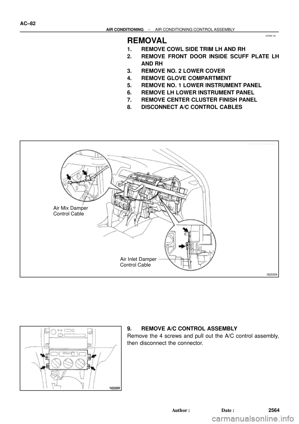
N20304
Air Mix Damper
Control Cable
Air Inlet Damper
Control Cable
N20289
AC±82
± AIR CONDITIONINGAIR CONDITIONING CONTROL ASSEMBLY
2564 Author�: Date�:
REMOVAL
1. REMOVE COWL SIDE TRIM LH AND RH
2. REMOVE FRONT DOOR INSIDE SCUFF PLATE LH
AND RH
3. REMOVE NO. 2 LOWER COVER
4. REMOVE GLOVE COMPARTMENT
5. REMOVE NO. 1 LOWER INSTRUMENT PANEL
6. REMOVE LH LOWER INSTRUMENT PANEL
7. REMOVE CENTER CLUSTER FINISH PANEL
8. DISCONNECT A/C CONTROL CABLES
9. REMOVE A/C CONTROL ASSEMBLY
Remove the 4 screws and pull out the A/C control assembly,
then disconnect the connector.
Page 916 of 4592

BO0MB±01
N20950
Instrument Panel ReinforcementNN
DD
No.2 Instrumental Panel Bracket
No.1 Instrumental Panel Bracket
No.2 Instrumental Panel Brace
QQH N
N
N
N
GG
NG
NOB
NN
Instrument Panel Brace Mount
No.1 Instrument
Panel BraceFront Pillar Garnish
Front Pillar
GarnishFront
Passenger
Airbag
Assembly
20 (200, 14)
No.2 Side Defroster Nozzle
Cowl Side Trim
Front Door Openin
g
Cover
Instrument Panel
C
Remote Control
Mirror Hole Base
Upper Column
CoverHazard Warning
Switch
Lower Finish
PlateGlove Compartment
Door Finish PlateFront Door
Inside Scuff Plate
FFF
FJ
Glove
Compartment
No.2 Lower
Panel A
A
Cluster Finish
Panel
Lower Column
Cover
Front Door
Opening
Cover
Cowl Side
TrimD
DD
D
D
F
AA
Lower Panel
InsertCoin
BoxCombination SwitchCombination
MeterRadio Assembly
Center Cluster
Finish Panel
A/C
Control Assembly
35 (360, 26)
Steering
Wheel
Pad Steering Wheel No.1 Lower
Panel
Front Door
Inside Scuff PlateFront Console
Box
Center Console
Upper PanelF
F
B
B
Rear Console
Box
N´m (kgf´cm, ft´lbf) : Specified torque BO±72
± BODYINSTRUMENT PANEL
2420 Author�: Date�:
INSTRUMENT PANEL
COMPONENTS
Page 920 of 4592
 Using a screwdriver, remove the glove compartment door
finish plate to")
N20988
N21023
7 Clips
N21024
6 Clips BO±76
± BODYINSTRUMENT PANEL
2424 Author�: Date�:
8. REMOVE GLOVE COMPARTMENT ASSEMBLY
(a) Using a screwdriver, remove the glove compartment door
finish plate to the glove compartment box inside.
NOTICE:
When handling the airbag connector, be careful not to dam-
age the airbag wire harness.
HINT:
Tape the screwdriver tip before use.
(b) Pull up and disconnect the airbag connector.
(c) Remove the 4 screws, bolt and glove compartment as-
sembly.
9. REMOVE CENTER CONSOLE UPPER PANEL
Using a screwdriver, remove the panel, then disconnect the
connector.
HINT:
Tape the screwdriver tip before use.
10. REMOVE REAR CONSOLE BOX
Remove the 2 bolts, 2 screws and the console box.
11. REMOVE CENTER CLUSTER FINISH PANEL
Using a screwdriver, remove the panel, then disconnect the
connector.
HINT:
Tape the screwdriver tip before using.
12. REMOVE FRONT CONSOLE BOX
Remove the 2 screws and the front console box.
13. REMOVE RADIO ASSEMBLY
14. REMOVE A/C CONTROL ASSEMBLY
(See page AC±82)
15. REMOVE HAZARD WARNING SWITCH
16. REMOVE CLUSTER FINISH PANEL
(a) Remove the 2 screws.
(b) Using a screwdriver, remove the panel.
HINT:
Tape the screwdriver tip before use.
17. REMOVE COMBINATION METER
18. REMOVE REMOTE CONTROL MIRROR HOLE BASE
Page 3825 of 4592

SPEEDOMETER/TACHOMETER NEEDLE MOVEMENT ± EL003-02Revised: December 13, 2002 February 11, 2000
Page 2 of 2
PREVIOUS PART NUMBERCURRENT PART NUMBERPART NAME
83220 XXXXXSameSpeedometer83220-XXXXXSameTachometer
TOOLS & MATERIALSQUANTITY
Double Sided Cotton Swab1
Distilled Water1 oz.
1. Remove the combination meter
assembly per repair manual
instructions.
2. Remove the window plate from the
instrument cluster.
3. Clean the entire surface of the needle
and needle stopper as illustrated.
Using one end of a double sided
cotton swab, clean the contact point
between the pointer and the stopper
pin on the speedometer and
tachometer with distilled water.
�Use only a new
, clean cotton
swab.
�Use only distilled
water.
�Use a new swab each time a part
is cleaned (one per speedometer,
one per tachometer).
NOTE:
� After cleaning, do not touch the
pointer needle or stopper pin.
� Do not blow dry the pointer or
stopper pin.
4. Use the opposite (dry) end of the
cotton swab to dry the previously
cleaned area.
5. Reassemble parts and assemble to
vehicle.
6. Confirm proper working condition of
speedometer and tachometer.
�Confirm no foreign material
entered the cluster while the
window plate was removed.
Parts
Information
Required
Tools &
Material
Repair
Procedure