Page 25 of 4592
AC21V±01
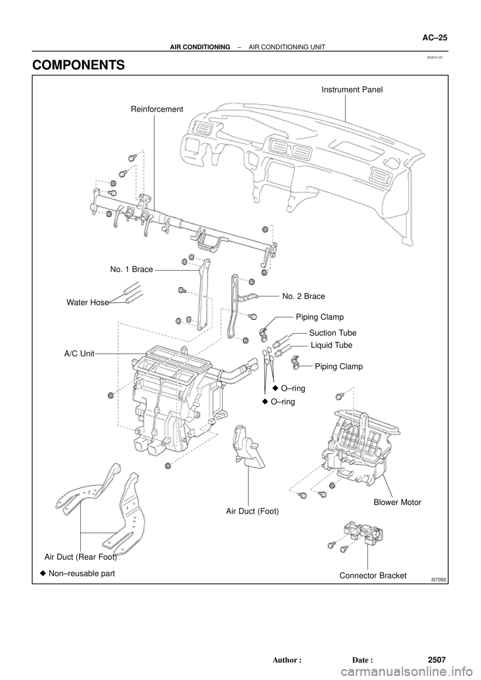
I07050
ReinforcementInstrument Panel
No. 1 Brace
No. 2 Brace
A/C Unit
Piping Clamp
Suction Tube
Liquid Tube
Piping Clamp
� O±ring� O±ring
Air Duct (Rear Foot)
Air Duct (Foot)Blower Motor
Connector Bracket � Non±reusable partWater Hose
± AIR CONDITIONINGAIR CONDITIONING UNIT
AC±25
2507 Author�: Date�:
COMPONENTS
Page 27 of 4592

AC21W±01
N20288
N20237
Water Hose
MarkingUpper
LH
Hose ClipRH Heater Radiator Pipe
45 ± 10°
Lower
I09160
± AIR CONDITIONINGAIR CONDITIONING UNIT
AC±27
2509 Author�: Date�:
REMOVAL
1. DISCHARGE REFRIGERANT FROM REFRIGERATION
SYSTEM
HINT:
At the time of installation, please refer to the following item.
Evacuate air from refrigeration system.
Charge system with refrigerant and inspect for leakage of refrig-
erant.
Specified amount: 800 ± 50 g (28.22 ± 1.76 oz.)
2. DRAIN ENGINE COOLANT FROM RADIATOR
HINT:
It is not necessary to drain out all the coolant.
3. DISCONNECT WATER HOSE FROM HEATER RADIA-
TOR PIPES
(a) Using pliers, grip the claws of the hose clip and slide the
hose clip along the hose.
(b) Disconnect the water hose.
HINT:
At the time of installation, please refer to the following items.
�Push the water hose onto the heater radiator pipe as far
as ridge on the pipe and install the hose clip.
�Install the hose clip in a position, as shown in the illustra-
tion.
4. REMOVE BLOWER UNIT (See page AC±35)
5. REMOVE INSTRUMENT PANEL AND REINFORCE-
MENT (See page BO±75)
6. DISCONNECT LIQUID AND SUCTION TUBES
(a) Using SST, remove the 2 piping clamps.
SST 09870±00015 (Suction tube)
09870±00025 (Liquid tube)
Page 57 of 4592
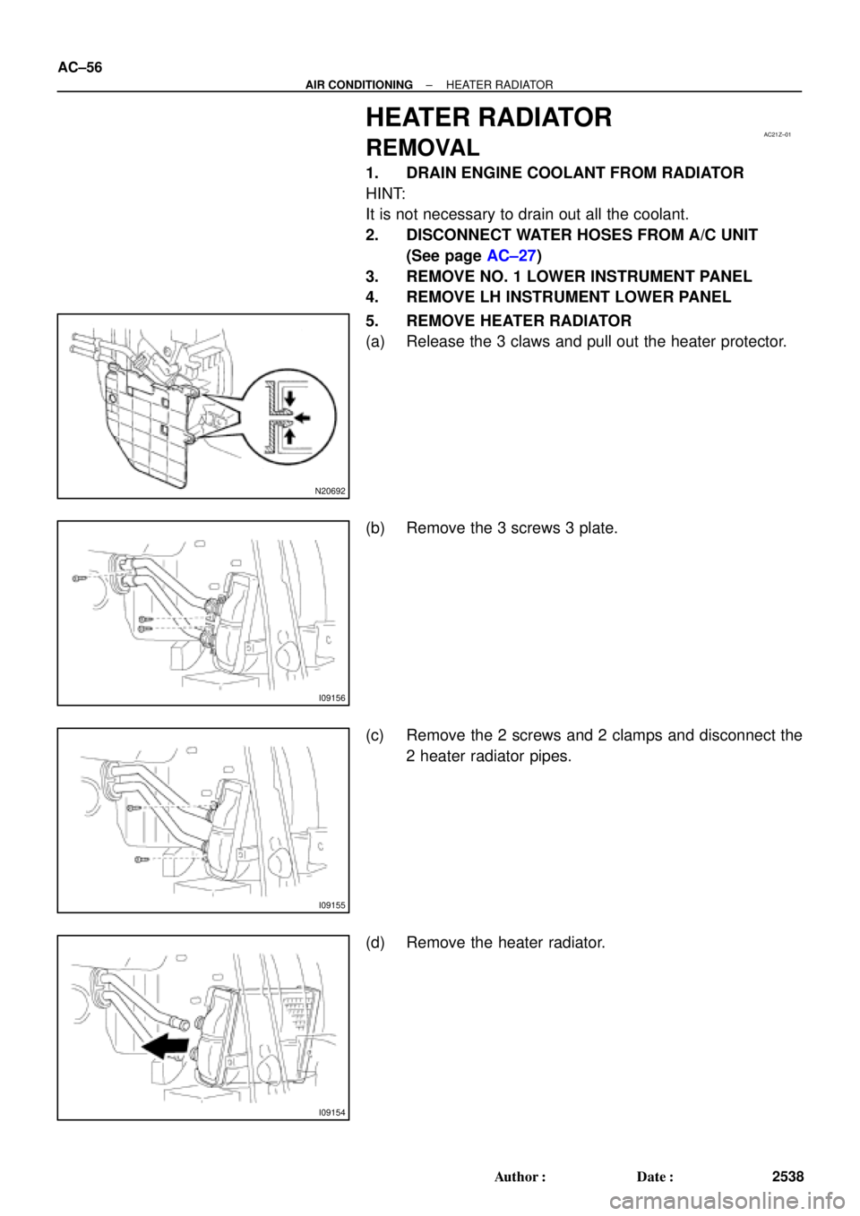
AC21Z±01
N20692
I09156
I09155
I09154
AC±56
± AIR CONDITIONINGHEATER RADIATOR
2538 Author�: Date�:
HEATER RADIATOR
REMOVAL
1. DRAIN ENGINE COOLANT FROM RADIATOR
HINT:
It is not necessary to drain out all the coolant.
2. DISCONNECT WATER HOSES FROM A/C UNIT
(See page AC±27)
3. REMOVE NO. 1 LOWER INSTRUMENT PANEL
4. REMOVE LH INSTRUMENT LOWER PANEL
5. REMOVE HEATER RADIATOR
(a) Release the 3 claws and pull out the heater protector.
(b) Remove the 3 screws 3 plate.
(c) Remove the 2 screws and 2 clamps and disconnect the
2 heater radiator pipes.
(d) Remove the heater radiator.
Page 66 of 4592
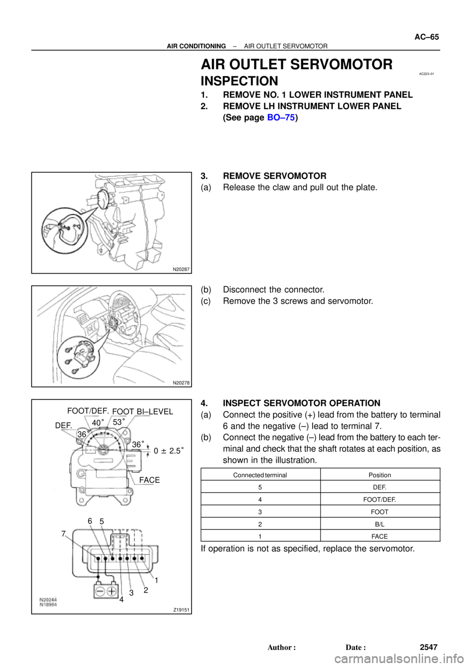
AC223±01
N20287
N20278
Z19151
DEF.FOOT/DEF.
FOOT BI±LEVEL
FACE
1
2
3
4 5 6
736°
0 ± 2.5° 36° 40°53°
± AIR CONDITIONINGAIR OUTLET SERVOMOTOR
AC±65
2547 Author�: Date�:
AIR OUTLET SERVOMOTOR
INSPECTION
1. REMOVE NO. 1 LOWER INSTRUMENT PANEL
2. REMOVE LH INSTRUMENT LOWER PANEL
(See page BO±75)
3. REMOVE SERVOMOTOR
(a) Release the claw and pull out the plate.
(b) Disconnect the connector.
(c) Remove the 3 screws and servomotor.
4. INSPECT SERVOMOTOR OPERATION
(a) Connect the positive (+) lead from the battery to terminal
6 and the negative (±) lead to terminal 7.
(b) Connect the negative (±) lead from the battery to each ter-
minal and check that the shaft rotates at each position, as
shown in the illustration.
Connected terminalPosition
5DEF.
4FOOT/DEF.
3FOOT
2B/L
1FACE
If operation is not as specified, replace the servomotor.
Page 67 of 4592
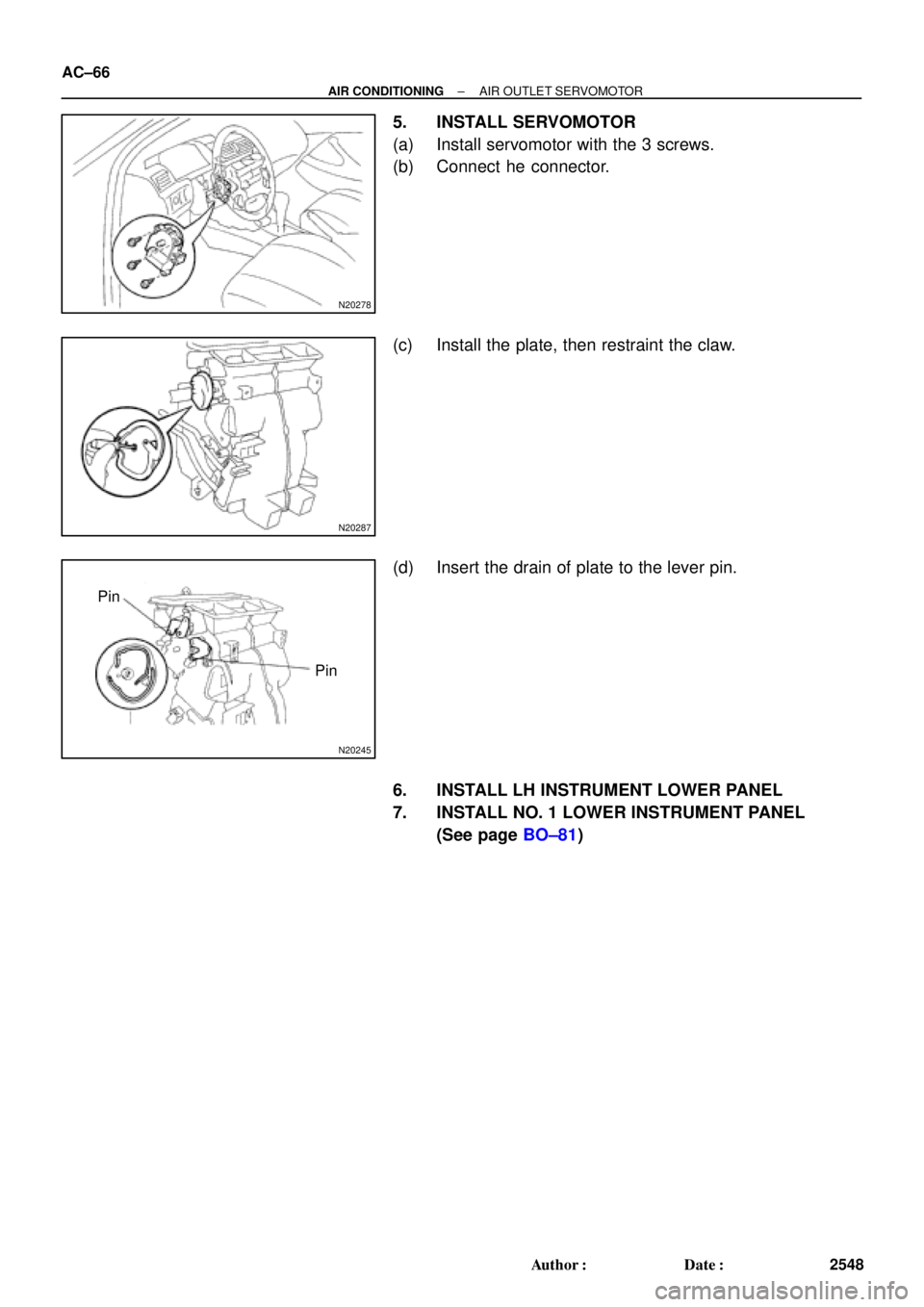
N20278
N20287
N20245
Pin
Pin AC±66
± AIR CONDITIONINGAIR OUTLET SERVOMOTOR
2548 Author�: Date�:
5. INSTALL SERVOMOTOR
(a) Install servomotor with the 3 screws.
(b) Connect he connector.
(c) Install the plate, then restraint the claw.
(d) Insert the drain of plate to the lever pin.
6. INSTALL LH INSTRUMENT LOWER PANEL
7. INSTALL NO. 1 LOWER INSTRUMENT PANEL
(See page BO±81)
Page 82 of 4592
AC0ND±02
Z19017
LH Lower Instrument
Panel
No.1 Lower Finish
Panel
Cowl Side Trim
Front Door Inside
Scuff PlateCenter Cluster Finish Panel
A/C Control Assembly
Glove Compartment
Cowl Side Trim
Air Inlet Damper Control Cable
Air Inlet Control Lever
Mode Switch
A/C Switch
Defogger Switch
Heater Control
Name Sheet
Heater Control Knob Heater Control BaseBlower Speed Control
SwitchFront Door Inside Scuff Plate
± AIR CONDITIONINGAIR CONDITIONING CONTROL ASSEMBLY
AC±81
2563 Author�: Date�:
COMPONENTS
Page 83 of 4592
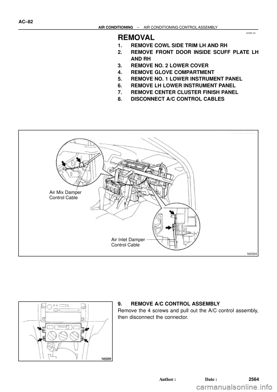
AC0NE±02
N20304
Air Mix Damper
Control Cable
Air Inlet Damper
Control Cable
N20289
AC±82
± AIR CONDITIONINGAIR CONDITIONING CONTROL ASSEMBLY
2564 Author�: Date�:
REMOVAL
1. REMOVE COWL SIDE TRIM LH AND RH
2. REMOVE FRONT DOOR INSIDE SCUFF PLATE LH
AND RH
3. REMOVE NO. 2 LOWER COVER
4. REMOVE GLOVE COMPARTMENT
5. REMOVE NO. 1 LOWER INSTRUMENT PANEL
6. REMOVE LH LOWER INSTRUMENT PANEL
7. REMOVE CENTER CLUSTER FINISH PANEL
8. DISCONNECT A/C CONTROL CABLES
9. REMOVE A/C CONTROL ASSEMBLY
Remove the 4 screws and pull out the A/C control assembly,
then disconnect the connector.
Page 592 of 4592
BE0A0±03
Z19043
Engine Room Relay Block No.1
Engine Room Junction
Block No.2
Engine Room Relay Block No.2
Instrument Panel Junction Block No.1
Turn Signal Flasher
± BODY ELECTRICALPOWER SOURCE
BE±11
2231 Author�: Date�:
POWER SOURCE
LOCATION