Page 1141 of 4592
CO066±03
± COOLING (5S±FE)COOLANT
CO±1
1575 Author�: Date�:
COOLANT
INSPECTION
HINT:
Check the coolant level when the engine is cold.
1. CHECK ENGINE COOLANT LEVEL AT RADIATOR RESERVOIR
The engine coolant level should be between the ºLOWº and ºFULLº lines.
If low, check for leaks and add ºToyota Long Life Coolantº or equivalent up to the ºFULLº line.
2. CHECK ENGINE COOLANT QUALITY
(a) Remove the radiator cap.
CAUTION:
To avoid the danger of being burned, do not remove the radiator cap while the engine and radiator
are still hot, as fluid and steam can be blown out under pressure.
(b) There should not be any excessive deposits of rust or scale around the radiator cap or radiator filler
hole, and the coolant should be free from oil.
If excessively dirty, replace the coolant.
(c) Reinstall the radiator cap.
Page 1142 of 4592
CO067±03
Z18990
Radiator Drain Plug
Engine Drain Plug CO±2
± COOLING (5S±FE)COOLANT
1576 Author�: Date�:
REPLACEMENT
1. DRAIN ENGINE COOLANT
(a) Remove the radiator cap.
CAUTION:
To avoid the danger of being burned, do not remove the ra-
diator cap while the engine and radiator are still hot, as fluid
and steam can be blown out under pressure.
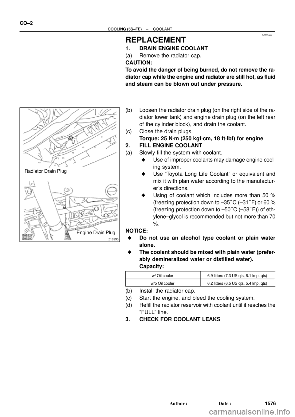
(b) Loosen the radiator drain plug (on the right side of the ra-
diator lower tank) and engine drain plug (on the left rear
of the cylinder block), and drain the coolant.
(c) Close the drain plugs.
Torque: 25 N´m (250 kgf´cm, 18 ft´lbf) for engine
2. FILL ENGINE COOLANT
(a) Slowly fill the system with coolant.
�Use of improper coolants may damage engine cool-
ing system.
�Use ºToyota Long Life Coolantº or equivalent and
mix it with plan water according to the manufactur-
er's directions.
�Using of coolant which includes more than 50 %
(freezing protection down to ±35°C (±31°F) or 60 %
(freezing protection down to ±50°C (±58°F)) of eth-
ylene±glycol is recommended but not more than 70
%.
NOTICE:
�Do not use an alcohol type coolant or plain water
alone.
�The coolant should be mixed with plain water (prefer-
ably demineralized water or distilled water).
Capacity:
w/ Oil cooler6.9 litters (7.3 US qts, 6.1 lmp. qts)
w/o Oil cooler6.2 litters (6.5 US qts, 5.4 lmp. qts)
(b) Install the radiator cap.
(c) Start the engine, and bleed the cooling system.
(d) Refill the radiator reservoir with coolant until it reaches the
ºFULLº line.
3. CHECK FOR COOLANT LEAKS
Page 1158 of 4592
CO06J±04
S05955
CO±18
± COOLING (5S±FE)RADIATOR
1592 Author�: Date�:
REMOVAL
1. DRAIN ENGINE COOLANT
2. REMOVE RADIATOR ASSEMBLY
(a) Disconnect the No.1 electric cooling fan connector.
(b) Disconnect the No.2 electric cooling fan connector.
(c) Disconnect the ECT switch connector for the electric cool-
ing fan.
(d) Disconnect the upper radiator hose from the radiator.
(e) Disconnect the lower radiator hose from the water inlet.
(f) Disconnect the radiator reservoir hose from the radiator.
(g) A/T:
Disconnect the 2 oil cooler hoses from the oil cooler pipes.
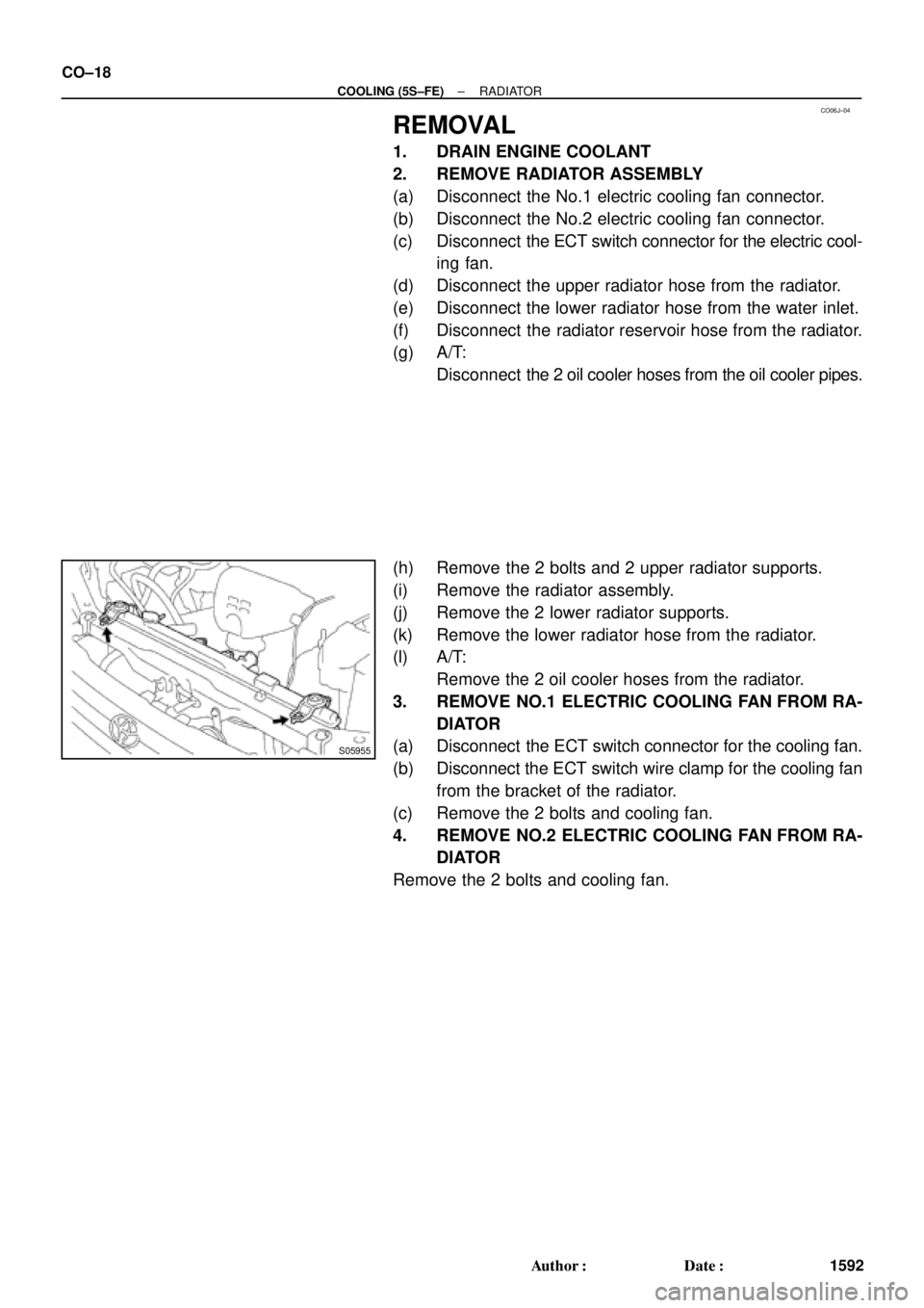
(h) Remove the 2 bolts and 2 upper radiator supports.
(i) Remove the radiator assembly.
(j) Remove the 2 lower radiator supports.
(k) Remove the lower radiator hose from the radiator.
(l) A/T:
Remove the 2 oil cooler hoses from the radiator.
3. REMOVE NO.1 ELECTRIC COOLING FAN FROM RA-
DIATOR
(a) Disconnect the ECT switch connector for the cooling fan.
(b) Disconnect the ECT switch wire clamp for the cooling fan
from the bracket of the radiator.
(c) Remove the 2 bolts and cooling fan.
4. REMOVE NO.2 ELECTRIC COOLING FAN FROM RA-
DIATOR
Remove the 2 bolts and cooling fan.
Page 1163 of 4592
CO06M±03
S05955
± COOLING (5S±FE)RADIATOR
CO±23
1597 Author�: Date�:
INSTALLATION
1. INSTALL NO.1 ELECTRIC COOLING FAN TO RADIA-
TOR
(a) Attach the lower side of the cooling fan to the bracket of
the radiator.
(b) Install the cooling fan with the 2 bolts.
(c) Connect the ECT switch connector for the cooling fan.
(d) Install the ECT switch wire clamp for the cooling fan to the
bracket of the radiator.
Torque: 5.0 N´m (50 kgf´cm, 44 in.´lbf)
2. INSTALL NO.2 ELECTRIC COOLING FAN TO RADIA-
TOR
(a) Attach the lower side of the cooling fan to the bracket of
the radiator.
(b) Install the cooling fan with the 2 bolts.
Torque: 5.0 N´m (50 kgf´cm, 44 in.´lbf)
3. INSTALL RADIATOR ASSEMBLY
(a) Install the lower radiator hose to the radiator.
(b) A/T:
Install the 2 oil cooler hoses to the radiator.
(c) Install the 2 lower radiator supports to the radiator.
(d) Attach the 2 lower radiator supports on the radiator to the
body brackets.
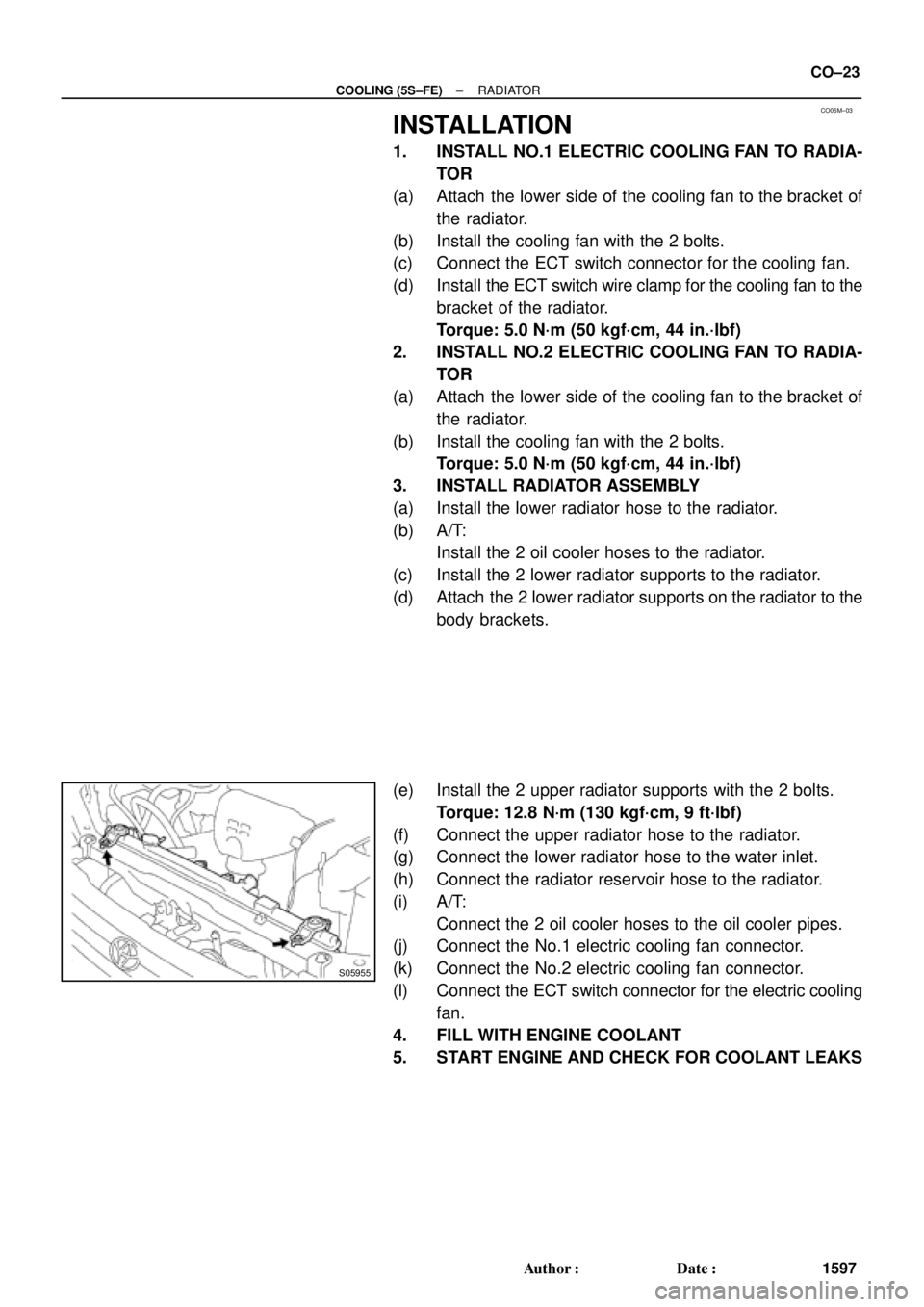
(e) Install the 2 upper radiator supports with the 2 bolts.
Torque: 12.8 N´m (130 kgf´cm, 9 ft´lbf)
(f) Connect the upper radiator hose to the radiator.
(g) Connect the lower radiator hose to the water inlet.
(h) Connect the radiator reservoir hose to the radiator.
(i) A/T:
Connect the 2 oil cooler hoses to the oil cooler pipes.
(j) Connect the No.1 electric cooling fan connector.
(k) Connect the No.2 electric cooling fan connector.
(l) Connect the ECT switch connector for the electric cooling
fan.
4. FILL WITH ENGINE COOLANT
5. START ENGINE AND CHECK FOR COOLANT LEAKS
Page 1175 of 4592
CO03B±04
± COOLING (1MZ±FE)COOLANT
CO±1
1609 Author�: Date�:
COOLANT
INSPECTION
1. CHECK ENGINE COOLANT LEVEL AT RADIATOR RESERVOIR
The engine coolant level should be between the ºLOWº and ºFULLº lines, when the engine is cold.
If low, check for leaks and add ''Toyota Long Life Coolantº or Equivalent up to the ºFULLº line.
2. CHECK ENGINE COOLANT QUALITY
(a) Remove the radiator cap from the water outlet.
CAUTION:
To avoid the danger of being burned, do not remove the radiator cap while the engine and radiator
are still hot, as fluid and steam can be blown out under pressure.
(b) There should not be any excessive deposits of rust or scale around the radiator cap or water outlet
filler hole, and the coolant should be free from oil.
If excessively dirty, clean the coolant passages and replace the coolant.
(c) Reinstall the radiator cap.
Page 1176 of 4592
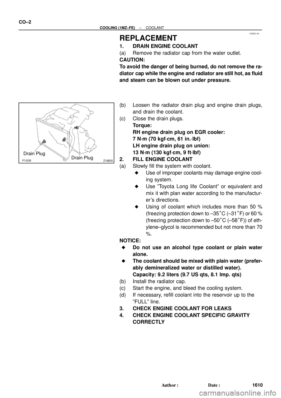
CO03C±04
Z18835
Drain Plug
Drain Plug CO±2
± COOLING (1MZ±FE)COOLANT
1610 Author�: Date�:
REPLACEMENT
1. DRAIN ENGINE COOLANT
(a) Remove the radiator cap from the water outlet.
CAUTION:
To avoid the danger of being burned, do not remove the ra-
diator cap while the engine and radiator are still hot, as fluid
and steam can be blown out under pressure.
(b) Loosen the radiator drain plug and engine drain plugs,
and drain the coolant.
(c) Close the drain plugs.
Torque:
RH engine drain plug on EGR cooler:
7 N´m (70 kgf´cm, 61 in.´lbf)
LH engine drain plug on union:
13 N´m (130 kgf´cm, 9 ft´lbf)
2. FILL ENGINE COOLANT
(a) Slowly fill the system with coolant.
�Use of improper coolants may damage engine cool-
ing system.
�Use ºToyota Long life Coolantº or equivalent and
mix it with plan water according to the manufactur-
er's directions.
�Using of coolant which includes more than 50 %
(freezing protection down to ±35°C (±31°F) or 60 %
(freezing protection down to ±50°C (±58°F)) of eth-
ylene±glycol is recommended but not more than 70
%.
NOTICE:
�Do not use an alcohol type coolant or plain water
alone.
�The coolant should be mixed with plain water (prefer-
ably demineralized water or distilled water).
Capacity: 9.2 liters (9.7 US qts, 8.1 lmp. qts)
(b) Install the radiator cap.
(c) Start the engine, and bleed the cooling system.
(d) If necessary, refill coolant into the reservoir up to the
ºFULLº line.
3. CHECK ENGINE COOLANT FOR LEAKS
4. CHECK ENGINE COOLANT SPECIFIC GRAVITY
CORRECTLY
Page 1177 of 4592
CO03D±04
A06654
RH Fender Apron Seal
Generator Drive BeltEngine Moving
Control Rod
RH Engine Mounting Stay
No.2 RH Engine
Mounting Bracket
Ground Strap PS Pump Drive Belt
Engine Coolant Reservoir Hose
: Specified torqueNo.2 RH Engine
Mounting Stay (M/T)
64 (650, 47)
32 (320, 23)
64 (650, 47)
N´m (kgf´cm, ft´lbf)
± COOLING (1MZ±FE)WATER PUMP
CO±3
1611 Author�: Date�:
WATER PUMP
COMPONENTS
Page 2237 of 4592

DI±86
± DIAGNOSTICSENGINE
DTC P1190 Fuel Pressure Regulator Malfunction
CIRCUIT DESCRIPTION
The fuel pressure regulator regulates the fuel pressure by reducing the pressure of the compressed fuel from
the fuel tank to the fuel injection pressure, which is 785 kPa (8 kgf/cm
2, 114 psi).
Similar to the fuel shutoff valve for the fuel tank, a fuel shutoff valve is provided on the fuel inlet side of the
fuel pressure regulator to shutoff the supply of fuel when the engine is stopped or during abnormal condi-
tions.
A reservoir that traps the moisture and oil in the fuel is provided on the low pressure side.
A built±in relief valve is provided to protect the parts located on the low pressure side.
While the fuel pressure is being reduced by the fuel pressure regulator, the Joule±Thompson effect
associated with the expansion of the fuel causes the fuel pressure regulator to be cooled excessively, exert-
ing unfavorable influence on the rubber parts such as diaphragms and fuel hoses.
Therefore, to raise the fuel temperature, a water passage is provided in the fuel pressure regulator to allow
the engine coolant to warm the regulator.
DTC No.DTC Detecting ConditionTrouble Area
P1190After engine is warmed up, detection of pressure control
malfunction (2 trip detection logic)
�Open or short in fuel shutoff valve circuit for fuel tank
�Fuel shutoff valve for fuel tank
�Open or short in fuel shutoff valve circuit for fuel pressure
regulator
�Fuel shutoff valve for fuel pressure regulator
�Fuel fuel pressure regulator
�Open or short in fuel shutoff valve circuit for fuel delivery
pipe
�Fuel shutoff valve for fuel delivery pipe
�ECM
DI64X±01