Page 9 of 4592

± AIR CONDITIONINGAIR CONDITIONING SYSTEM
AC±9
2491 Author�: Date�:
3. INSPECT IDLE±UP SPEED
(a) Warm up engine.
(b) Inspect idle±up speed when the these conditions are es-
tablished.
�Warm up engine
�Blower speed control switch at ºHIº position
�A/C switch ON
�Temperature control dial at ºCOOLº position
Magnetic clutch conditionIdle±up speed
Magnetic clutch not engaged700 ± 50 rpm
Magnetic clutch engaged700 ± 50 rpm
If idle speed is not as specified, check ISC valve and air intake
system.
4. INSPECT FOR LEAKAGE OF REFRIGERANT
(a) Perform in these conditions:
�Stop engine.
�Secure good ventilation (If not the gas leak detector
may react to volatile gases witch are not refrigerant,
such as evaporated gasoline and exhaust gas.)
�Repeat the test 2 or 3 times.
�Make sure that there is some refrigerant remaining
in the refrigeration system.
When compressor is OFF: approx. 392 ± 588 kPa
(4 ± 6 kgf/ cm
2, 57 ± 85 psi)
(b) Bring the gas leak detector close to the drain hose before
performing the test.
HINT:
�After the blower motor stopped, leave the cooling unit for
more than 15 minutes.
�Expose the gas leak detector sensor the under the drain
hose.
�When bring the gas leak detector close to the drain hose,
make sure that the gas leak detector does not react to the
volatile gases.
If such reaction is unavoidable, the vehicle must be lifted up.
(c) If gas leak is not detected on the drain hose, remove the
blower resistor from the cooling unit. Then insert the gas
leak detector sensor into the unit and perform the test.
(d) Disconnect the connector and leave the pressure switch
for approx. 20 minutes. Then bring the gas leak detector
close to the pressure switch and perform the test.
(e) Bring the gas leak detector close to the refrigerant lines
and perform the test.
Page 13 of 4592
AC0LL±02
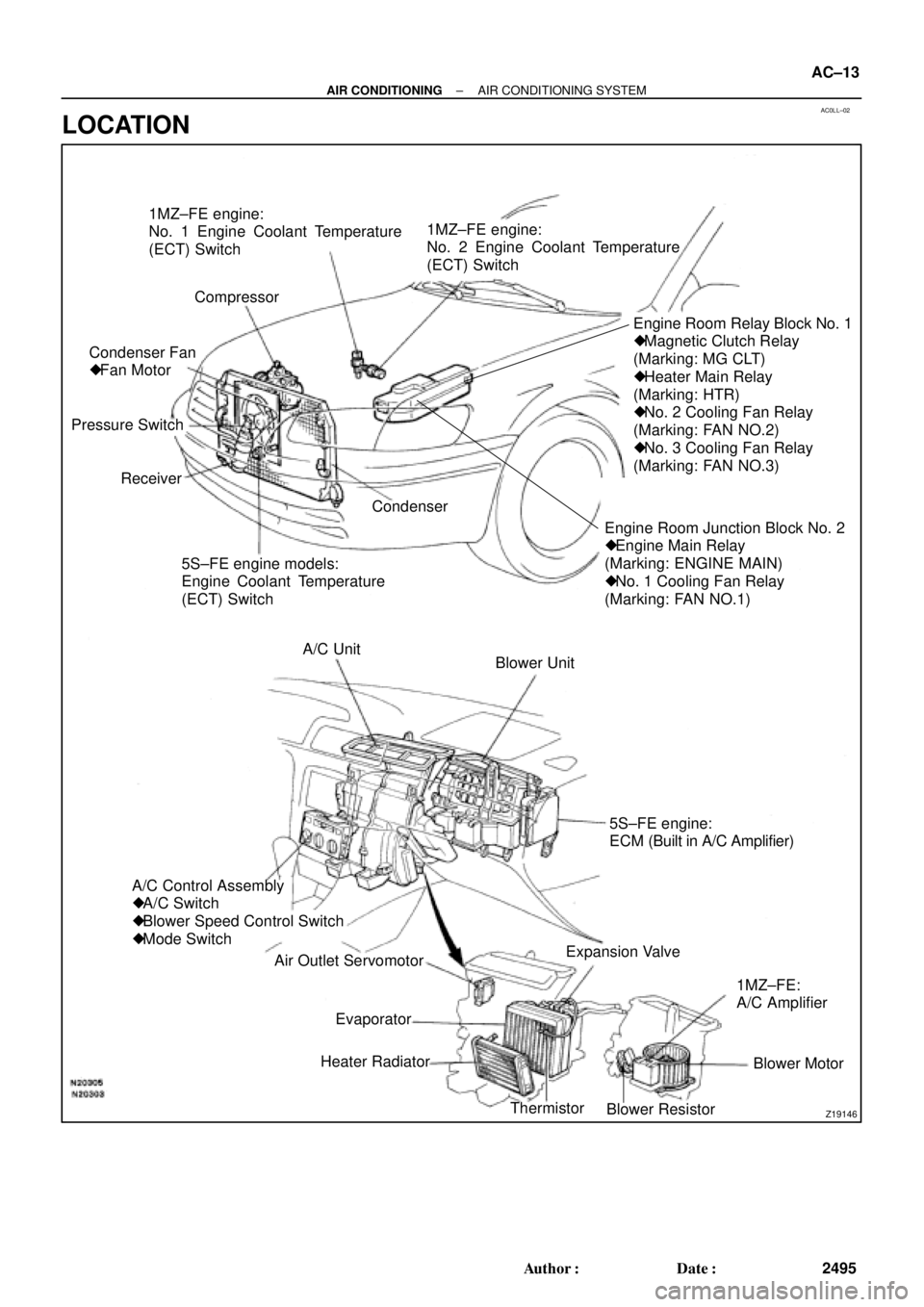
Z19146
1MZ±FE engine:
No. 1 Engine Coolant Temperature
(ECT) Switch
Compressor
Engine Room Junction Block No. 2
� Engine Main Relay
(Marking: ENGINE MAIN)
� No. 1 Cooling Fan Relay
(Marking: FAN NO.1)Engine Room Relay Block No. 1
� Magnetic Clutch Relay
(Marking: MG CLT)
� Heater Main Relay
(Marking: HTR)
� No. 2 Cooling Fan Relay
(Marking: FAN NO.2)
� No. 3 Cooling Fan Relay
(Marking: FAN NO.3)
5S±FE engine models:
Engine Coolant Temperature
(ECT) Switch Receiver Pressure SwitchCondenser Fan
� Fan Motor1MZ±FE engine:
No. 2 Engine Coolant Temperature
(ECT) Switch
Condenser
Blower Unit A/C Unit
A/C Control Assembly
� A/C Switch
� Blower Speed Control Switch
� Mode Switch
Air Outlet Servomotor
Heater Radiator
Thermistor
Blower ResistorBlower Motor 1MZ±FE:
A/C Amplifier Expansion Valve5S±FE engine:
ECM (Built in A/C Amplifier)
Evaporator
± AIR CONDITIONINGAIR CONDITIONING SYSTEM
AC±13
2495 Author�: Date�:
LOCATION
Page 14 of 4592

AC21T±01
AC±14
± AIR CONDITIONINGTROUBLESHOOTING
2496 Author�: Date�:
TROUBLESHOOTING
PROBLEM SYMPTOMS TABLE
Use the table below to help you find the cause of the problem. The numbers indicate the priority of the likely
cause of the problem. Check each part in order. If necessary, replace these parts.
SymptomSuspect AreaSee page
No blower operation
4. HTR Fuse
5. Heater main relay
6. Blower motor
7. Blower resistor
8. Blower speed control switch
9. Wire harness±
AC±70
AC±63
AC±64
AC±84
±
No air temperature control1. Engine coolant volume
2. A/C control assembly±
AC±80
No air inlet control1. A/C control assemblyAC±80
No air outlet control
1. HTR Fuse
2. Air outlet servomotor
3. Mode switch±
AC±65
AC±84
No compressor operation
1. Refrigerant volume
2. A.C Fuse
3. HTR Fuse
4. Magnetic clutch relay
5. Magnetic clutch
6. Compressor
7. Pressure switch
8. Heater main relay
9. Blower speed control switch
10.A/C switch
11. *1 ECM
*
2 A/C amplifier
12.Wire harness
AC±3
±
±
AC±71
AC±39
AC±39
AC±67
AC±70
AC±84
AC±84
DI±218
AC±88
±
No compressor operates intermittently
1. Refrigerant volume
2. Condenser fan
3. Pressure switch
4. *1 ECM
*2 A/C amplifier
5. Thermistor
6. Wire harnessAC±3
AC±74
AC±67
DI±218
AC±88
AC±24
±
No cool air comes out
1. Refrigerant volume
2. Refrigerant pressure
3. Drive belt
4. Compressor lock sensor
5. Magnetic clutch
6. Compressor
7. Pressure switch
8. Thermistor
9. A/C switch
10.*1 ECM
*2 A/C amplifier
11. Wire harnessAC±3
AC±3
AC±16
AC±16
AC±39
AC±39
AC±67
AC±24
AC±84
DI±218
AC±88
±
Page 15 of 4592
± AIR CONDITIONINGTROUBLESHOOTING
AC±15
2497 Author�: Date�:
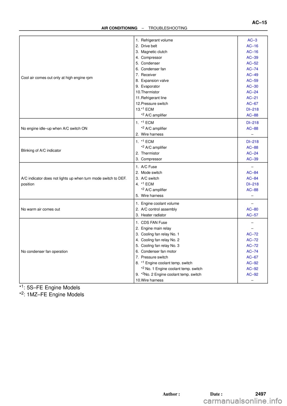
Cool air comes out only at high engine rpm
1. Refrigerant volume
2. Drive belt
3. Magnetic clutch
4. Compressor
5. Condenser
6. Condenser fan
7. Receiver
8. Expansion valve
9. Evaporator
10.Thermistor
11. Refrigerant line
12.Pressure switch
13.*
1 ECM
*2 A/C amplifier
AC±3
AC±16
AC±16
AC±39
AC±52
AC±74
AC±49
AC±59
AC±30
AC±24
AC±21
AC±67
DI±218
AC±88
No engine idle±up when A/C switch ON
1. *1 ECM
*2 A/C amplifier
2. Wire harness
DI±218
AC±88
±
Blinking of A/C indicator
1. *1 ECM
*2 A/C amplifier
2. Thermistor
3. Compressor
DI±218
AC±88
AC±24
AC±39
A/C indicator does not lights up when turn mode switch to DEF.
position
1. A/C Fuse
2. Mode switch
3. A/C switch
4. *
1 ECM
*2 A/C amplifier
5. Wire harness
±
AC±84
AC±84
DI±218
AC±88
±
No warm air comes out
1. Engine coolant volume
2. A/C control assembly
3. Heater radiator±
AC±80
AC±57
No condenser fan operation
1. CDS FAN Fuse
2. Engine main relay
3. Cooling fan relay No. 1
4. Cooling fan relay No. 2
5. Cooling fan relay No. 3
6. Condenser fan motor
7. Pressure switch
8. *
1 Engine coolant temp. switch
*2 No. 1 Engine coolant temp. switch
9. *2No. 2 Engine coolant temp. switch
10.Wire harness
±
±
AC±72
AC±72
AC±72
AC±74
AC±67
AC±92
AC±92
AC±92
±
*1: 5S±FE Engine Models
*
2: 1MZ±FE Engine Models
Page 71 of 4592
I09189
Heater Main
Relay
AC224±01
Z19533
34
5
1212 34 5 AC±70
± AIR CONDITIONINGHEATER MAIN RELAY
2552 Author�: Date�:
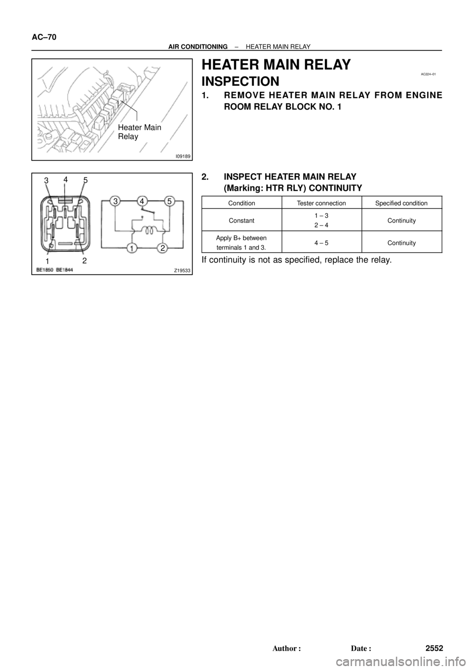
HEATER MAIN RELAY
INSPECTION
1. REMOVE HEATER MAIN RELAY FROM ENGINE
ROOM RELAY BLOCK NO. 1
2. INSPECT HEATER MAIN RELAY
(Marking: HTR RLY) CONTINUITY
ConditionTester connectionSpecified condition
Constant1 ± 3
2 ± 4Continuity
Apply B+ between
terminals 1 and 3.4 ± 5Continuity
If continuity is not as specified, replace the relay.
Page 72 of 4592
I09189
Magnetic Clutch
Relay
AC225±01
Z18060
35
1212 3
5
± AIR CONDITIONINGMAGNETIC CLUTCH RELAY
AC±71
2553 Author�: Date�:
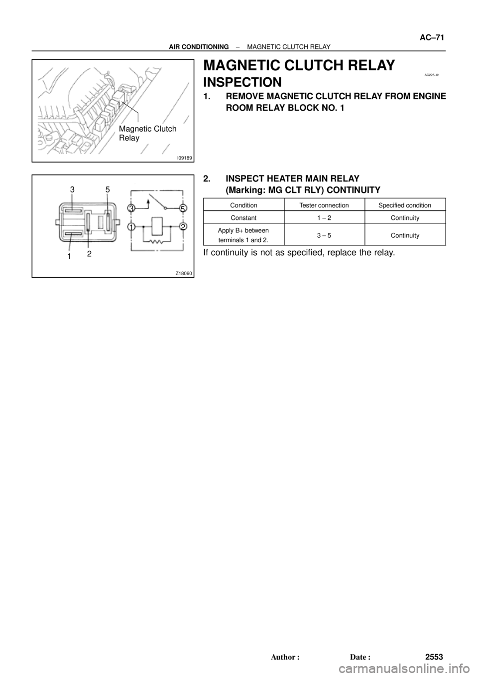
MAGNETIC CLUTCH RELAY
INSPECTION
1. REMOVE MAGNETIC CLUTCH RELAY FROM ENGINE
ROOM RELAY BLOCK NO. 1
2. INSPECT HEATER MAIN RELAY
(Marking: MG CLT RLY) CONTINUITY
ConditionTester connectionSpecified condition
Constant1 ± 2Continuity
Apply B+ between
terminals 1 and 2.3 ± 5Continuity
If continuity is not as specified, replace the relay.
Page 584 of 4592
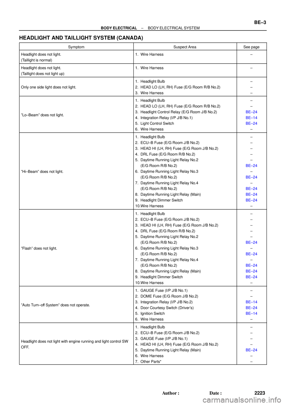
± BODY ELECTRICALBODY ELECTRICAL SYSTEM
BE±3
2223 Author�: Date�:
HEADLIGHT AND TAILLIGHT SYSTEM (CANADA)
SymptomSuspect AreaSee page
Headlight does not light.
(Taillight is normal)1. Wire Harness±
Headlight does not light.
(Taillight does not light up)1. Wire Harness±
Only one side light does not light.
1. Headlight Bulb
2. HEAD LO (LH, RH) Fuse (E/G Room R/B No.2)
3. Wire Harness±
±
±
ºLo±Beamº does not light.
1. Headlight Bulb
2. HEAD LO (LH, RH) Fuse (E/G Room R/B No.2)
3. Headlight Control Relay (E/G Room J/B No.2)
4. Integration Relay (I/P J/B No.1)
5. Light Control Switch
6. Wire Harness±
±
BE±24
BE±14
BE±24
±
ºHi±Beamº does not light.
1. Headlight Bulb
2. ECU±B Fuse (E/G Room J/B No.2)
3. HEAD HI (LH, RH) Fuse (E/G Room J/B No.2)
4. DRL Fuse (E/G Room R/B No.2)
5. Daytime Running Light Relay No.2
(E/G Room R/B No.2)
6. Daytime Running Light Relay No.3
(E/G Room R/B No.2)
7. Daytime Running Light Relay No.4
(E/G Room R/B No.2)
8. Daytime Running Light Relay (Main)
9. Headlight Dimmer Switch
10.Wire Harness±
±
±
±
±
BE±24
±
BE±24
±
BE±24
BE±24
BE±24
±
ºFlashº does not light.
1. Headlight Bulb
2. ECU±B Fuse (E/G Room J/B No.2)
3. HEAD HI (LH, RH) Fuse (E/G Room J/B No.2)
4. DRL Fuse (E/G Room R/B No.2)
5. Daytime Running Light Relay No.2
(E/G Room R/B No.2)
6. Daytime Running Light Relay No.3
(E/G Room R/B No.2)
7. Daytime Running Light Relay No.4
(E/G Room R/B No.2)
8. Daytime Running Light Relay (Main)
9. Headlight Dimmer Switch
10.Wire Harness±
±
±
±
±
BE±24
±
BE±24
±
BE±24
BE±24
BE±24
±
ºAuto Turn±off Systemº does not operate.
1. GAUGE Fuse (I/P J/B No.1)
2. DOME Fuse (E/G Room J/B No.2)
3. Integration Relay (I/P J/B No.2)
4. Door Courtesy Switch (Driver's)
5. Ignition Switch
6. Wire Harness±
±
BE±14
BE±24
BE±14
±
Headlight does not light with engine running and light control SW
OFF.
1. Headlight Bulb
2. ECU±B Fuse (E/G Room J/B No.2)
3. GAUGE Fuse (I/P J/B No.1)
4. HEAD HI (LH, RH) Fuse (E/G Room J/B No.2)
5. Daytime Running Light Relay (Main)
6. Wire Harness
7. Other Parts*±
±
±
±
BE±24
±
±
Page 606 of 4592

I08219
Wire harness side:
± BODY ELECTRICALHEADLIGHT AND TAILLIGHT SYSTEM
BE±25
2245 Author�: Date�:
6. INSPECT DAYTIME RUNNING LIGHT RELAY (MAIN)
CIRCUIT
Disconnect the connector from the relay and inspect the con-
nector on the wire harness side.
Tester connectionConditionSpecified condition
2 ± GroundLight control switch position OFF or TAILNo continuity
2 ± GroundLight control switch position HEADContinuity
3 ± GroundHeadlight dimmer switch position
Low beamNo continuity
3 ± GroundHeadlight dimmer switch position
High beam of FlashContinuity
4 ± GroundBrake fluid level warning position OFFNo continuity
4 ± GroundBrake fluid level warning position ONContinuity
12 ± GroundConstantContinuity
14 ± GroundParking brake switch position OFF
(Parking brake lever released)No continuity
14 ± GroundParking brake switch position ON
(Parking brake lever pulled up)Continuity
17 ± GroundLight control switch position OFF or HEADNo voltage
17 ± GroundLight control switch position TAILContinuity
20 ± GroundConstantContinuity
21 ± GroundConstantContinuity
13 ± GroundEngine StopNo voltage
13 ± GroundEngine RunningBattery positive voltage
16 ± GroundConstantBattery positive voltage
18 ± GroundGround terminal 19Battery positive voltage
19 ± GroundConstantBattery positive voltage
22 ± GroundConstantBattery positive voltage
23 ± GroundIgnition switch position LOCK or ACCNo voltage
23 ± GroundIgnition switch position ON or STARTBattery positive voltage
If circuit is as specified, try replacing the relay with a new one.
If circuit is not as specified, inspect the circuits connected to oth-
er parts.