Page 9 of 4592
 Warm up engine.
(b) Inspect idle±up speed when the these conditions are es-
tablished.
�Warm up en")
± AIR CONDITIONINGAIR CONDITIONING SYSTEM
AC±9
2491 Author�: Date�:
3. INSPECT IDLE±UP SPEED
(a) Warm up engine.
(b) Inspect idle±up speed when the these conditions are es-
tablished.
�Warm up engine
�Blower speed control switch at ºHIº position
�A/C switch ON
�Temperature control dial at ºCOOLº position
Magnetic clutch conditionIdle±up speed
Magnetic clutch not engaged700 ± 50 rpm
Magnetic clutch engaged700 ± 50 rpm
If idle speed is not as specified, check ISC valve and air intake
system.
4. INSPECT FOR LEAKAGE OF REFRIGERANT
(a) Perform in these conditions:
�Stop engine.
�Secure good ventilation (If not the gas leak detector
may react to volatile gases witch are not refrigerant,
such as evaporated gasoline and exhaust gas.)
�Repeat the test 2 or 3 times.
�Make sure that there is some refrigerant remaining
in the refrigeration system.
When compressor is OFF: approx. 392 ± 588 kPa
(4 ± 6 kgf/ cm
2, 57 ± 85 psi)
(b) Bring the gas leak detector close to the drain hose before
performing the test.
HINT:
�After the blower motor stopped, leave the cooling unit for
more than 15 minutes.
�Expose the gas leak detector sensor the under the drain
hose.
�When bring the gas leak detector close to the drain hose,
make sure that the gas leak detector does not react to the
volatile gases.
If such reaction is unavoidable, the vehicle must be lifted up.
(c) If gas leak is not detected on the drain hose, remove the
blower resistor from the cooling unit. Then insert the gas
leak detector sensor into the unit and perform the test.
(d) Disconnect the connector and leave the pressure switch
for approx. 20 minutes. Then bring the gas leak detector
close to the pressure switch and perform the test.
(e) Bring the gas leak detector close to the refrigerant lines
and perform the test.
Page 111 of 4592
AX03G±01
Q10053
14 (145, 10)
No.1 Exhaust Pipe Support BracketClip Engine Hood
Air Cleaner Assembly
14 (145, 10)
Starter
Cruise Control Actuator
RH Drive Shaft
42 (430, 31)66 (670, 48)
39 (400, 29)
39 (400, 29)
39 (400, 29)
Hold Down Clamp
Manifold Stay
Stiffener
PlateBattery
Battery Tray � Snap Ring
�
32 (330, 24)
27 (280, 20)
Torque Converter
Clutch
x6
42 (430, 31)
42 (430, 31)
Stiffener Plate66 (670, 48)
42 (430, 31)
Exhaust
Manifold Stay66 (670, 48)
� Snap RingLH Drive Shaft
Plug for Line Pressure Test
Rear End Plate
15 (150, 11)
19 (195, 14)
25 (250, 18)
Oil Pan Insulator Shift Control Cable
N´m (kgf´cm, ft´lbf): Specified torque
� Non±reusable partTMMK
TMC
± AUTOMATIC TRANSAXLE (A140E)AUTOMATIC TRANSAXLE UNIT
AX±17
1910 Author�: Date�:
AUTOMATIC TRANSAXLE UNIT
COMPONENTS
Page 112 of 4592
RH Rear
Lower Brace
Steering Return Pipe
19 (195, 14)
FR Engine Mounting
Stabilizer Bar Link
Front Suspension
Member
�
Front Ex")
Q10054
RH Fender Apron seal
RR Engine Mounting
Stabilizer Bar
10 (100, 7)RH Rear
Lower Brace
Steering Return Pipe
19 (195, 14)
FR Engine Mounting
Stabilizer Bar Link
Front Suspension
Member
�
Front Exhaust Pipe
RH Front Lower Brace
LH Engine Mounting
66 (670, 48)
64 (650, 47)
39 (400, 29)
181 (1,850, 134)
LH Rear Lower Brace
32 (330, 24)
36 (370, 27)
181 (1,850, 134)
127 (1,300, 94)80 (820, 59)
TMC Made : 80 (820, 59)
TMMK Made :
Green Color Bolt : 66 (670, 48)
Silver Color Bolt : 44 (450, 32)
TMC Made : 80 (820, 59)
TMMK Made :
Green Color Bolt : 66 (670, 48)
Silver Color Bolt : 44 (450, 32)LH Front
Lower Brace
36 (370, 27)181 (1,850, 134)
56 (570, 41)
�
�� � Gasket
62 (630, 46)
Tie Rod End
Lock Nut Cap
Engine Under CoverLH Fender Liner � Gasket
�
Exhaust Pipe No.1 Support Bracket
33 (330, 24)
33 (330, 24)
Exhaust Pipe
ClampLH Fender Liner
LH Fender Apron Seal
� Cotter Pin
49 (500, 36)
294 (3,000, 217)
Center Engine Under Cover
N´m (kgf´cm, ft´lbf): Specified torque
� Non±reusable part AX±18
± AUTOMATIC TRANSAXLE (A140E)AUTOMATIC TRANSAXLE UNIT
1911 Author�: Date�:
Page 114 of 4592
AUTOMATIC TRANSAXLE UNIT
1913 Author�: Date�:
14. REMOVE EXHAUST MANIFOLD STAY
Remove the 2 bolts and exhaust manifold stay.
Torque: 42 N´m (")
Q10058
Q10059
Q00251
AX±20
± AUTOMATIC TRANSAXLE (A140E)AUTOMATIC TRANSAXLE UNIT
1913 Author�: Date�:
14. REMOVE EXHAUST MANIFOLD STAY
Remove the 2 bolts and exhaust manifold stay.
Torque: 42 N´m (430 kgf´cm, 31 ft´lbf)
15. REMOVE TRANSAXLE±TO±ENGINE BOLT
Torque: 66 N´m (670 kgf´cm, 48 ft´lbf)
16. REMOVE ENGINE HOOD
(a) Disconnect the washer pipe.
(b) Remove the 4 bolts and engine hood.
Torque: 14 N´m (145 kgf´cm, 10 ft´lbf)
17. RAISE AND SUPPORT VEHICLE SECURELY
18. REMOVE FRONT WHEELS
Torque: 103 N´m (1,050 kgf´cm, 76 ft´lbf)
19. REMOVE ENGINE UNDER COVER AND CENTER EN-
GINE UNDER COVER
20. DISCONNECT SHIFT CONTROL CABLE
(a) Remove the nut and disconnect the shift control cable
from the park/neutral position switch.
Torque: 15 N´m (150 kgf´cm, 11 ft´lbf)
(b) Remove the clip and disconnect the shift control cable
from the bracket.
21. REMOVE DIFFERENTIAL FLUID DRAIN PLUG AND
GASKET
HINT:
At the time of installation, please refer to the following item.
Replace the used gasket with a new gasket.
22. DRAIN DIFFERENTIAL FLUID
23. REMOVE LH AND RH FENDER APRON SEALS
24. REMOVE LH AND RH DRIVE SHAFTS
(See page SA±17)
Page 115 of 4592
AUTOMATIC TRANSAXLE UNIT
AX±21
1914 Author�: Date�:
25. REMOVE EXHAUST FRONT PIPE
(a) Remove the 2 nuts and exhaust front pipe clamp.
Torque:")
Q10060
Q00068
Q08532
Q10061
± AUTOMATIC TRANSAXLE (A140E)AUTOMATIC TRANSAXLE UNIT
AX±21
1914 Author�: Date�:
25. REMOVE EXHAUST FRONT PIPE
(a) Remove the 2 nuts and exhaust front pipe clamp.
Torque: 33 N´m (330 kgf´cm, 24 ft´lbf)
(b) Remove the 2 bolts and exhaust pipe No.1 support brack-
et.
Torque: 33 N´m (330 kgf´cm, 24 ft´lbf)
(c) Remove the 3 nuts.
Torque: 62 N´m (630 kgf´cm, 46 ft´lbf)
HINT:
At the time of installation, please refer to the following item.
Replace the used nuts with new ones.
(d) Remove the 2 bolts, nuts and front exhaust pipe.
Torque: 56 N´m (570 kgf´cm, 41 ft´lbf)
HINT:
At the time of installation, please refer to the following item.
Replace the used nuts with new ones.
(e) Remove the 2 gaskets.
HINT:
At the time of installation, please refer to the following item.
Replace the used gaskets with new ones.
26. REMOVE FRONT SIDE ENGINE MOUNTING INSULA-
TOR BOLT
Torque:
TMC made: 80 N´m (820 kgf´cm, 59 ft´lbf)
TMMK made:
Green color bolt: 66 N´m (670 kgf´cm, 48 ft´lbf)
Silver color bolt: 44 N´m (450 kgf´cm, 32 ft´lbf)
27. REMOVE REAR SIDE ENGINE MOUNTING NUT
(a) Remove the 2 grommets.
(b) Remove the 3 nuts.
Torque: 66 N´m (670 kgf´cm, 48 ft´lbf)
28. REMOVE LEFT SIDE TRANSAXLE MOUNTING NUT
(a) Remove the 2 grommets.
(b) Remove the 2 nuts.
Torque: 80 N´m (820 kgf´cm, 59 ft´lbf)
Page 117 of 4592
Q10172
Front
Q10064
Rear
Q10065
TMC : Bolt
TMMK : Nut
± AUTOMATIC TRANSAXLE (A140E)AUTOMATIC TRANSAXLE UNIT
AX±23
1916 Author�: Date�:
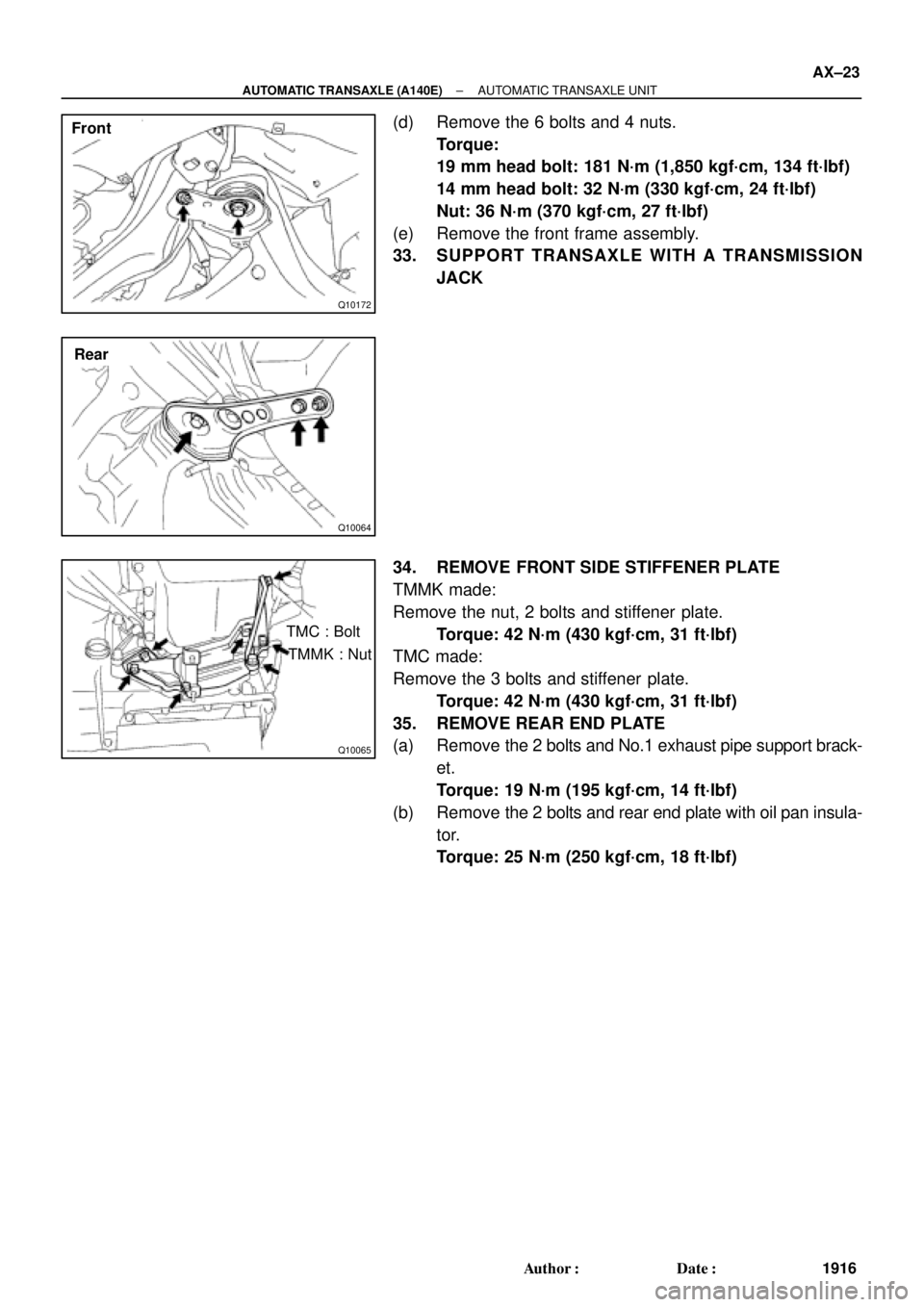
(d) Remove the 6 bolts and 4 nuts.
Torque:
19 mm head bolt: 181 N´m (1,850 kgf´cm, 134 ft´lbf)
14 mm head bolt: 32 N´m (330 kgf´cm, 24 ft´lbf)
Nut: 36 N´m (370 kgf´cm, 27 ft´lbf)
(e) Remove the front frame assembly.
33. SUPPORT TRANSAXLE WITH A TRANSMISSION
JACK
34. REMOVE FRONT SIDE STIFFENER PLATE
TMMK made:
Remove the nut, 2 bolts and stiffener plate.
Torque: 42 N´m (430 kgf´cm, 31 ft´lbf)
TMC made:
Remove the 3 bolts and stiffener plate.
Torque: 42 N´m (430 kgf´cm, 31 ft´lbf)
35. REMOVE REAR END PLATE
(a) Remove the 2 bolts and No.1 exhaust pipe support brack-
et.
Torque: 19 N´m (195 kgf´cm, 14 ft´lbf)
(b) Remove the 2 bolts and rear end plate with oil pan insula-
tor.
Torque: 25 N´m (250 kgf´cm, 18 ft´lbf)
Page 142 of 4592
AX03X±01
D01057
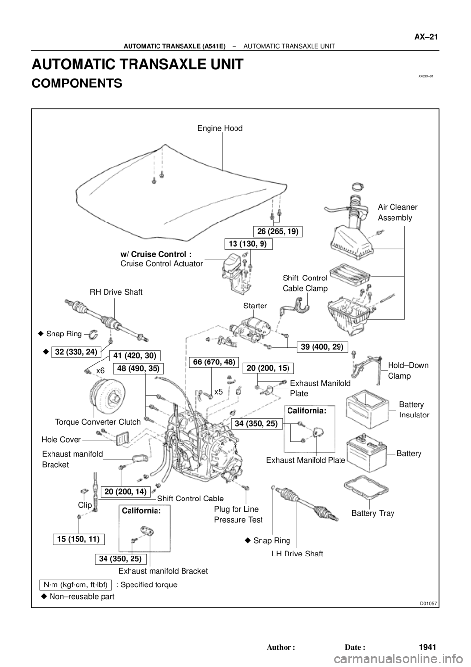
Engine Hood
Cruise Control Actuator
RH Drive ShaftAir Cleaner
Assembly
Shift Control Cable
LH Drive Shaft Plug for Line
Pressure TestBattery TrayBatteryBattery
Insulator � Snap Ring
Exhaust manifold
Bracket Hole CoverTorque Converter ClutchShift Control
Cable Clamp
Starter
x6
ClipHold±Down
Clamp
26 (265, 19)
15 (150, 11)
34 (350, 25)
39 (400, 29)
66 (670, 48)48 (490, 35)
32 (330, 24)41 (420, 30)
N´m (kgf´cm, ft´lbf) : Specified torque
� Non±reusable part� Snap Ring �
20 (200, 15)
20 (200, 14)
13 (130, 9)
x5Exhaust Manifold
Plate w/ Cruise Control :
California:
Exhaust Manifold Plate
34 (350, 25)
Exhaust manifold Bracket
California:
± AUTOMATIC TRANSAXLE (A541E)AUTOMATIC TRANSAXLE UNIT
AX±21
1941 Author�: Date�:
AUTOMATIC TRANSAXLE UNIT
COMPONENTS
Page 143 of 4592

Q10282
RH Fender Apron Seal
RH Rear Lower BraceRear Side Engine
Mounting InsulatorStabilizer Bar Link
Stabilizer Bar
LH Fender Apron Seal
LH Rear Lower Brace
Tie Rod End
Lock Cap
� Cotter Pin
� Gasket
� Cotter
Pin LH Front
Lower Brace
Exhaust Front Pipe
Support Bracket
RH Fender Liner
Center Engine Under Cover
Exhaust Front Pipe Support Stay Grommet Steering Return Pipe
� Gasket
� Gasket
80 (820, 59)
19 (195, 14)
39 (400, 29)
181 (1,850, 134)
36 (370, 27)
32 (330, 24)
10 (100, 7)
48 (490, 35)
49 (500, 36)
127 (1,300, 94)
294 (3,000, 217)
56 (570, 41)
33 (330, 24)62 (630, 46)
21 (210, 15) Green Color Bolt
80 (820, 59)
36 (370, 27)
181 (1,850, 134)
181 (1,850, 134)66 (670, 48)
Front Side Engine
Mounting Insulator
RH Front
Lower Brace
33 (330, 24)
LH Fender Liner
Engine Under Cover
N´m (kgf´cm, ft´lbf) : Specified torque
� Non±reusable part TMC Made:
80 (820, 59)
TMMK Made:
� Silver Color Bolt
62 (630, 46)
���
44 (450, 32)
Green Color Bolt
66 (670, 48) TMC Made:
80 (820, 59)
TMMK Made:
Silver Color Bolt
44 (450, 32)
AX±22
± AUTOMATIC TRANSAXLE (A541E)AUTOMATIC TRANSAXLE UNIT
1942 Author�: Date�:

No.1 Exhaust Pipe Support BracketClip Engine Hood
Air Cleaner Assembly
14 (145, 10)
Starter
Cruise Control Actuator
RH Drive Shaft
42 (430, 31)66 (670, 48)
39 (400, 29)
3")