Page 99 of 4592

14 (0.551)36 (1.417)
AT2711
Z10940
20
(0.787)mm (in.)
45
(1.772)50
(1.969)
AT3336
± AUTOMATIC TRANSAXLE (A140E)VALVE BODY ASSEMBLY
AX±5
1898 Author�: Date�:
V")
AX038±01
Q00073
AT0103
Z10944
mm (in.)
14 (0.551)36 (1.417)
AT2711
Z10940
20
(0.787)mm (in.)
45
(1.772)50
(1.969)
AT3336
± AUTOMATIC TRANSAXLE (A140E)VALVE BODY ASSEMBLY
AX±5
1898 Author�: Date�:
VALVE BODY ASSEMBLY
ON±VEHICLE REPAIR
1. DRAIN TRANSAXLE FLUID
2. REMOVE OIL PAN AND GASKET
NOTICE:
Some fluid will remain in the oil pan.
Remove the oil pan bolts, and carefully remove the oil pan as-
sembly. Discard the gasket.
3. EXAMINE PARTICLES IN PAN
Remove the magnets and use them to collect any steel chips.
Look carefully at the chips and particles in the pan and on the
magnet to anticipate what type of wear you will find in the trans-
axle.
�Steel (magnetic): bearing, gear and plate wear
�Brass (non±magnetic): bushing wear
4. REMOVE MANUAL VALVE BODY DETENT SPRING
AND MANUAL VALVE BODY
(a) Remove the detent spring on the manual valve body.
(b) Remove the manual valve body.
5. REMOVE OIL STRAINER AND OIL PIPE BRACKET
(a) Remove the 3 bolts and the oil strainer.
(b) Remove the 2 bolts and oil pipe bracket.
NOTICE:
Be careful as oil will come out of the strainer when it is re-
moved.
Page 102 of 4592

20
(0.78)
45
(1.772)50
(1.969)
AT3336
Z10944
mm (in.)
36 (1.417)
14 (0.551)
AT2711
Z10945
Magnets
AT2368
Q00073
AX±8
± AUTOMATIC TRANSAXLE (A140E)VALVE BODY ASSEMBLY
1901 Author�: Da")
Z10940
mm (in.)
20
(0.78)
45
(1.772)50
(1.969)
AT3336
Z10944
mm (in.)
36 (1.417)
14 (0.551)
AT2711
Z10945
Magnets
AT2368
Q00073
AX±8
± AUTOMATIC TRANSAXLE (A140E)VALVE BODY ASSEMBLY
1901 Author�: Date�:
17. INSTALL OIL STRAINER AND OIL PIPE BRACKET
(a) Install the 2 bolts and oil pipe bracket.
Torque: 10 N´m (100 kgf´cm, 7 ft´lbf)
(b) Install the 3 bolts and oil strainer.
Torque: 10 N´m (100 kgf´cm, 7 ft´lbf)
18. INSTALL MANUAL VALVE BODY DETENT SPRING
AND MANUAL VALVE BODY
(a) Align the manual valve with the pin on the manual shaft
lever.
(b) Lower the manual valve body into place.
(c) Temporarily install the 4 bolts first. Then, tighten them with
a torque wrench.
Torque: 10 N´m (100 kgf´cm, 7 ft´lbf)
(d) Place the detent spring on the manual valve body and
temporarily install the 2 bolts first.
Torque: 10 N´m (100 kgf´cm, 7 ft´lbf)
(e) Check that the manual valve lever is touching the center
of the detent spring tip roller.
19. INSTALL MAGNETS IN OIL PAN
NOTICE:
Make sure that the magnets do not interfere with the oil
pipes.
20. INSTALL OIL PAN AND GASKET
Install a new gasket and oil pan with the 15 bolts.
Torque: 4.9 N´m (50 kgf´cm, 43 in.´lbf)
21. FILL FLUID AND CHECK FLUID LEVEL
(See page DI±389)
Page 103 of 4592
200 mm
(7.87 in.)
± AUTOMATIC TRANSAXLE (A140E)THROTTLE CABLE
AX±9
1902 Author�: Date�:
THROTTLE CABLE
ON±VEHICLE REPAIR
1. DISCONNECT THROT")
AX039±01
Q10052
Q10339
0.8 ± 1.5 mm(0.031 ± 0.059 in.)200 mm
(7.87 in.)
± AUTOMATIC TRANSAXLE (A140E)THROTTLE CABLE
AX±9
1902 Author�: Date�:
THROTTLE CABLE
ON±VEHICLE REPAIR
1. DISCONNECT THROTTLE CABLE
(a) Disconnect the cable from the throttle linkage.
(b) Disconnect the cable from the cable clamps in the engine
compartment.
2. REMOVE PARK/NEUTRAL POSITION SWITCH
(See page AX±4)
3. REMOVE VALVE BODY (See page AX±5)
4. REMOVE THROTTLE CABLE
(a) Remove the retaining bolt and plate.
(b) Pull out the cable from the transaxle case.
5. IF THROTTLE CABLE IS NEW, STAKE STOPPER OR
PAINT MARK ON INNER CABLE
HINT:
New cable does not have a staked cable stopper.
(a) Bend the cable to ensure a radius of about 200 mm (7.87
in.).
(b) Pull the inner cable lightly until a slight resistance is felt,
and hold it there.
(c) Stake the stopper, 0.8 ± 1.5 mm (0.031 ± 0.059 in.) from
the end of the outer cable.
(d) Install a new O±ring to the throttle cable.
(e) Push in the throttle cable and install the retaining bolt.
6. INSTALL VALVE BODY (See page AX±5)
7. INSTALL PARK/NEUTRAL POSITION SWITCH
(See page AX±4)
8. CONNECT THROTTLE CABLE
9. FILL FLUID AND CHECK FLUID LEVEL
(See page DI±389)
10. ADJUST THROTTLE CABLE (See page DI±389)
Page 105 of 4592
Q00394
SST
AX03B±01
Q00247
SST
± AUTOMATIC TRANSAXLE (A140E)DIFFERENTIAL OIL SEAL
AX±11
1904 Author�: Date�:
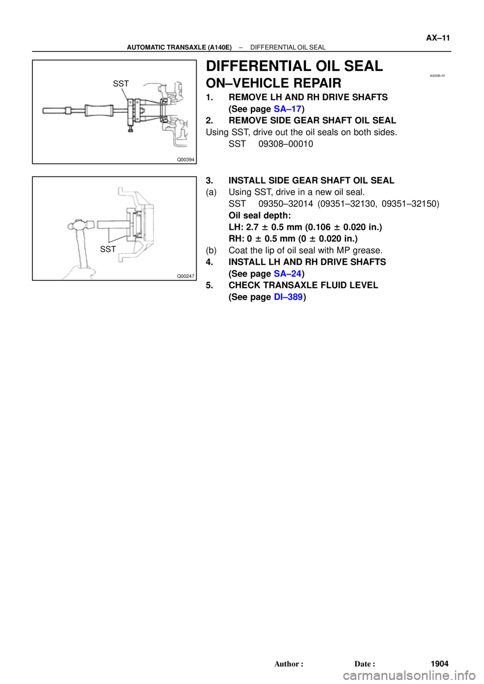
DIFFERENTIAL OIL SEAL
ON±VEHICLE REPAIR
1. REMOVE LH AND RH DRIVE SHAFTS
(See page SA±17)
2. REMOVE SIDE GEAR SHAFT OIL SEAL
Using SST, drive out the oil seals on both sides.
SST 09308±00010
3. INSTALL SIDE GEAR SHAFT OIL SEAL
(a) Using SST, drive in a new oil seal.
SST 09350±32014 (09351±32130, 09351±32150)
Oil seal depth:
LH: 2.7 ± 0.5 mm (0.106 ± 0.020 in.)
RH: 0 ± 0.5 mm (0 ± 0.020 in.)
(b) Coat the lip of oil seal with MP grease.
4. INSTALL LH AND RH DRIVE SHAFTS
(See page SA±24)
5. CHECK TRANSAXLE FLUID LEVEL
(See page DI±389)
Page 114 of 4592
AUTOMATIC TRANSAXLE UNIT
1913 Author�: Date�:
14. REMOVE EXHAUST MANIFOLD STAY
Remove the 2 bolts and exhaust manifold stay.
Torque: 42 N´m (")
Q10058
Q10059
Q00251
AX±20
± AUTOMATIC TRANSAXLE (A140E)AUTOMATIC TRANSAXLE UNIT
1913 Author�: Date�:
14. REMOVE EXHAUST MANIFOLD STAY
Remove the 2 bolts and exhaust manifold stay.
Torque: 42 N´m (430 kgf´cm, 31 ft´lbf)
15. REMOVE TRANSAXLE±TO±ENGINE BOLT
Torque: 66 N´m (670 kgf´cm, 48 ft´lbf)
16. REMOVE ENGINE HOOD
(a) Disconnect the washer pipe.
(b) Remove the 4 bolts and engine hood.
Torque: 14 N´m (145 kgf´cm, 10 ft´lbf)
17. RAISE AND SUPPORT VEHICLE SECURELY
18. REMOVE FRONT WHEELS
Torque: 103 N´m (1,050 kgf´cm, 76 ft´lbf)
19. REMOVE ENGINE UNDER COVER AND CENTER EN-
GINE UNDER COVER
20. DISCONNECT SHIFT CONTROL CABLE
(a) Remove the nut and disconnect the shift control cable
from the park/neutral position switch.
Torque: 15 N´m (150 kgf´cm, 11 ft´lbf)
(b) Remove the clip and disconnect the shift control cable
from the bracket.
21. REMOVE DIFFERENTIAL FLUID DRAIN PLUG AND
GASKET
HINT:
At the time of installation, please refer to the following item.
Replace the used gasket with a new gasket.
22. DRAIN DIFFERENTIAL FLUID
23. REMOVE LH AND RH FENDER APRON SEALS
24. REMOVE LH AND RH DRIVE SHAFTS
(See page SA±17)
Page 119 of 4592
AX03I±01
AT3412
± AUTOMATIC TRANSAXLE (A140E)AUTOMATIC TRANSAXLE UNIT
AX±25
1918 Author�: Date�:
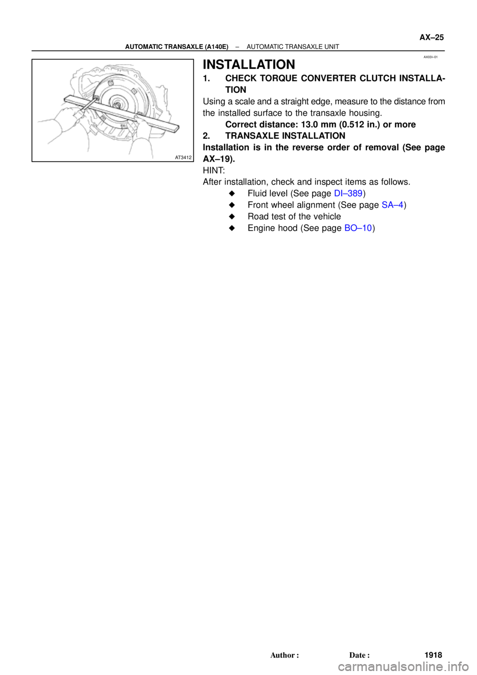
INSTALLATION
1. CHECK TORQUE CONVERTER CLUTCH INSTALLA-
TION
Using a scale and a straight edge, measure to the distance from
the installed surface to the transaxle housing.
Correct distance: 13.0 mm (0.512 in.) or more
2. TRANSAXLE INSTALLATION
Installation is in the reverse order of removal (See page
AX±19).
HINT:
After installation, check and inspect items as follows.
�Fluid level (See page DI±389)
�Front wheel alignment (See page SA±4)
�Road test of the vehicle
�Engine hood (See page BO±10)
Page 128 of 4592
VALVE BODY ASSEMBLY
AX±7
1927 Author�: Date�:
VALVE BODY ASSEMBLY
ON±VEHICLE REPAIR
1. DRAIN ATF
Using a hexagon wrench,")
AX03Q±02
AT3785
AT0103
D01019
Q05728
Connector
± AUTOMATIC TRANSAXLE (A541E)VALVE BODY ASSEMBLY
AX±7
1927 Author�: Date�:
VALVE BODY ASSEMBLY
ON±VEHICLE REPAIR
1. DRAIN ATF
Using a hexagon wrench, remove the drain plug and fluid into
the suitable container.
2. REMOVE OIL PAN AND GASKET
NOTICE:
Some fluid will remain in the oil pan.
Remove oil pan bolts, and carefully remove the pan assembly.
Discard the gasket.
3. EXAMINE PARTICLES IN PAN
Remove the magnets and use them to collect any steel chips.
Look at the chips and particles in the pan and magnet carefully
to anticipate what type of wear you will find in the transaxle.
�Steel (magnetic): bearing, gear and plate wear
�Brass (non±magnetic): bushing wear
4. REMOVE OIL STRAINER AND APPLY PIPE BRACKET
(a) Remove the 3 bolts and oil strainer.
NOTICE:
Be careful as oil will come out of the strainer when it is re-
moved.
(b) Remove the 3 bolts and apply pipe bracket.
5. REMOVE OIL PIPES
Pry up both pipe ends with a large screwdriver and remove the
5 pipes.
6. DISCONNECT SOLENOID CONNECTORS
Page 133 of 4592
Z19256
BA
B A
AT3741
AT3785
AX±12
± AUTOMATIC TRANSAXLE (A541E)VALVE BODY ASSEMBLY
1932 Author�: Date�:
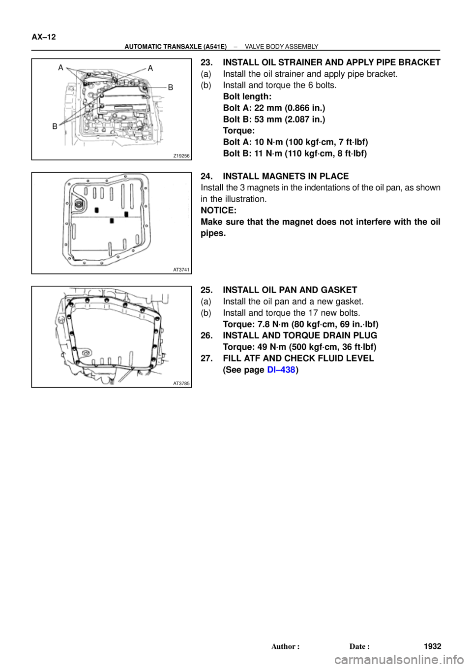
23. INSTALL OIL STRAINER AND APPLY PIPE BRACKET
(a) Install the oil strainer and apply pipe bracket.
(b) Install and torque the 6 bolts.
Bolt length:
Bolt A: 22 mm (0.866 in.)
Bolt B: 53 mm (2.087 in.)
Torque:
Bolt A: 10 N´m (100 kgf´cm, 7 ft´lbf)
Bolt B: 11 N´m (110 kgf´cm, 8 ft´lbf)
24. INSTALL MAGNETS IN PLACE
Install the 3 magnets in the indentations of the oil pan, as shown
in the illustration.
NOTICE:
Make sure that the magnet does not interfere with the oil
pipes.
25. INSTALL OIL PAN AND GASKET
(a) Install the oil pan and a new gasket.
(b) Install and torque the 17 new bolts.
Torque: 7.8 N´m (80 kgf´cm, 69 in.´lbf)
26. INSTALL AND TORQUE DRAIN PLUG
Torque: 49 N´m (500 kgf´cm, 36 ft´lbf)
27. FILL ATF AND CHECK FLUID LEVEL
(See page DI±438)