Page 390 of 4592
AUTOMATIC TRANSAXLEVALVE BODY ±
AX±84
10. INSTALL LOWER VALVE BODY COVER GASKETS
AND NO.2 PLATE
Position a new gasket and plate and then another new
gasket.
HINT: Both gaskets are identical.
11. INSTALL LOWER VALVE BODY COVER
(a) Position the lower valve body cover.
(b) Install and finger tighten the 5 bolts.
HINT: Each bolt length is indicated below.
Bolt length
Bolt A: 47 mm (1.850 in.)
Bolt B: 14 mm (0.551 in.)
12. INSTALL PRESSURE RELIEF VALVE
13. TIGHTEN BOLTS OF UPPER AND LOWER VALVE BO-
DIES
(a) Tighten the 16 bolts in the lower valve body.
Torque: 6.6 N´m (67 kgf´cm, 58 in.´lbf)
(b) Tighten the 3 bolts in the upper valve body.
Torque: 6.6 N´m (67 kgf´cm, 58 in.´lbf)
14. INSTALL B0 ACCUMULATOR ASSEMBLY
(a) Coat new O±rings with ATF and install them to the piston.
(b) Install the spring and piston into the cylinder.
Spring dimensions
mm (in.)
ColorFree lengthCoil outer diameter
Inner White47.5 (1.870)18.9 (0.744)
Outer None16.3 (0.642)20.7 (0.815)
Page 426 of 4592
AUTOMATIC TRANSAXLECOMPONENT PARTS INSTALLATION ±
AX±120
(b) Using SST, measure the piston stroke while applying and
releasing compressed air (392±785 kPa, 4±8 kgf/cm
2,
57±114 psi).
SST 09240±00020
Piston stroke:
2.0±3.5 mm (0.079±0.138 in.)
If the stroke is more than specified, replace the piston rod
with a longer one.
Piston rod length:
95.2 mm (3.748 in.)
96.3 mm (3.791 in.)
If the still more than standard value, replace the brake
band with a new one.
HYDRAULIC CONTROL UNIT INSTALLATION
1. INSTALL ACCUMULATOR PISTONS AND SPRINGS
(a) Install the new O±rings to the pistons.
(b) Install the springs and pistons into the bores.
Spring dimensions
mm (in.)
Spring ColorFree length
C2Yellow/Purple51.8 (2.039)
B2None88.2 (3.473)
B2None70.3 (2.767)
C1None73.6 (2.898)
(c) Place the cover with a new gasket and gradually tighten
the bolts a little at a time in sequence.
Torque: 10 N´m (100 kgf´cm, 7 ft´lbf)
AX0U3±02
Page 533 of 4592
AUTOMATIC TRANSAXLEVALVE BODY ±
AX±84
10. INSTALL LOWER VALVE BODY COVER GASKETS
AND NO.2 PLATE
Position a new gasket and plate and then another new
gasket.
HINT: Both gaskets are identical.
11. INSTALL LOWER VALVE BODY COVER
(a) Position the lower valve body cover.
(b) Install and finger tighten the 5 bolts.
HINT: Each bolt length is indicated below.
Bolt length
Bolt A: 47 mm (1.850 in.)
Bolt B: 14 mm (0.551 in.)
12. INSTALL PRESSURE RELIEF VALVE
13. TIGHTEN BOLTS OF UPPER AND LOWER VALVE BO-
DIES
(a) Tighten the 16 bolts in the lower valve body.
Torque: 6.6 N´m (67 kgf´cm, 58 in.´lbf)
(b) Tighten the 3 bolts in the upper valve body.
Torque: 6.6 N´m (67 kgf´cm, 58 in.´lbf)
14. INSTALL B0 ACCUMULATOR ASSEMBLY
(a) Coat new O±rings with ATF and install them to the piston.
(b) Install the spring and piston into the cylinder.
Spring dimensions
mm (in.)
ColorFree lengthCoil outer diameter
Inner White47.5 (1.870)18.9 (0.744)
Outer None16.3 (0.642)20.7 (0.815)
Page 569 of 4592
AUTOMATIC TRANSAXLECOMPONENT PARTS INSTALLATION ±
AX±120
(b) Using SST, measure the piston stroke while applying and
releasing compressed air (392±785 kPa, 4±8 kgf/cm
2,
57±114 psi).
SST 09240±00020
Piston stroke:
2.0±3.5 mm (0.079±0.138 in.)
If the stroke is more than specified, replace the piston rod
with a longer one.
Piston rod length:
95.2 mm (3.748 in.)
96.3 mm (3.791 in.)
If the still more than standard value, replace the brake
band with a new one.
HYDRAULIC CONTROL UNIT INSTALLATION
1. INSTALL ACCUMULATOR PISTONS AND SPRINGS
(a) Install the new O±rings to the pistons.
(b) Install the springs and pistons into the bores.
Spring dimensions
mm (in.)
Spring ColorFree length
C2Yellow/Purple51.8 (2.039)
B2None88.2 (3.473)
B2None70.3 (2.767)
C1None73.6 (2.898)
(c) Place the cover with a new gasket and gradually tighten
the bolts a little at a time in sequence.
Torque: 10 N´m (100 kgf´cm, 7 ft´lbf)
AX0U3±02
Page 2656 of 4592
CYLINDER BLOCK
EM±105
1277 Author�: Date�:
(b) Using a micrometer, measure the piston diameter at right
angle")
A07352
20.5 mm
S01546
SST
S05573
Cut Position
Pry
S05572
SST
± ENGINE MECHANICAL (5S±FE)CYLINDER BLOCK
EM±105
1277 Author�: Date�:
(b) Using a micrometer, measure the piston diameter at right
angles to the piston pin center line, 20.5 mm (0.807 in.)
from the piston head.
(c) Calculate the amount of each cylinder is to be rebored as
follows:
Size to be rebored = P + C ± H
P = Piston diameter
C = Piston oil clearance
0.175 ± 0.195 mm (0.0068 ± 0.0076 in.)
H = Allowance for honing
0.02 mm (0.0008 in.) or less
(d) Bore and hone the cylinders to calculated dimensions.
Maximum honing: 0.02 mm (0.0008 in.)
NOTICE:
Excess honing will destroy the finished roundness.
3. REPLACE CRANKSHAFT FRONT OIL SEAL
HINT:
There are 2 methods ((a) and (b)) to replace the oil seal.
(a) If the oil pump is removed from the cylinder block:
(1) Using a screwdriver and hammer, tap out the oil
seal.
(2) Using SST and a hammer, tap in a new oil seal until
its surface is flush with the oil pump body edge.
SST 09226±10010
(3) Apply MP grease to the oil seal lip.
(b) If the oil pump is installed to the cylinder block:
(1) Using a knife, cut off the oil seal lip.
(2) Using a screwdriver, pry out the oil seal.
NOTICE:
Be careful not to damage the crankshaft. Tape the screw-
driver tip.
(3) Apply MP grease to a new oil seal lip.
(4) Using SST and a hammer, tap in the oil seal until its
surface is flush with the oil pump body edge.
SST 09226±10010
Page 2812 of 4592
N20620
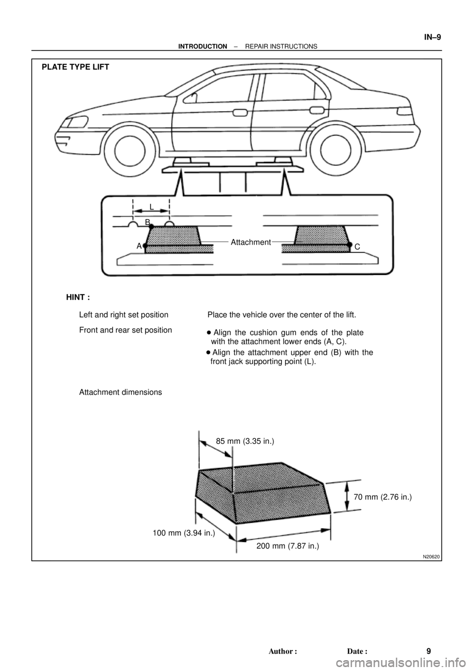
PLATE TYPE LIFT
L
B
AAttachment
C
HINT :
Left and right set position
Front and rear set positionPlace the vehicle over the center of the lift.
� Align the cushion gum ends of the plate
with the attachment lower ends (A, C).
� Align the attachment upper end (B) with the
front jack supporting point (L).
Attachment dimensions
85 mm (3.35 in.)
100 mm (3.94 in.)70 mm (2.76 in.)
200 mm (7.87 in.)
± INTRODUCTIONREPAIR INSTRUCTIONS
IN±9
9 Author�: Date�:
Page 2855 of 4592
N20620
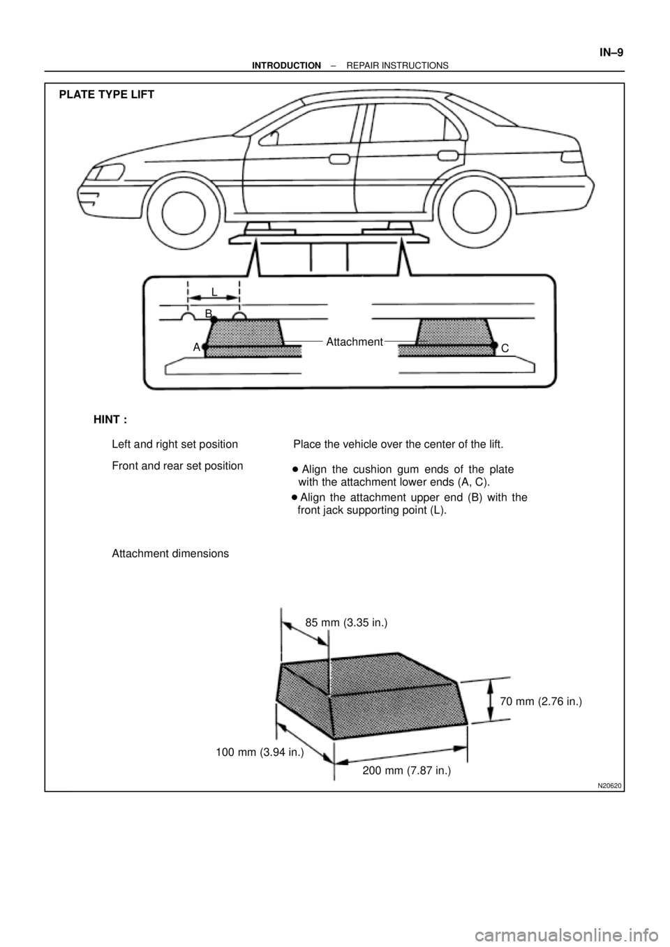
PLATE TYPE LIFT
L
B
AAttachment
C
HINT :
Left and right set position
Front and rear set positionPlace the vehicle over the center of the lift.
� Align the cushion gum ends of the plate
with the attachment lower ends (A, C).
� Align the attachment upper end (B) with the
front jack supporting point (L).
Attachment dimensions
85 mm (3.35 in.)
100 mm (3.94 in.)70 mm (2.76 in.)
200 mm (7.87 in.)
± INTRODUCTIONREPAIR INSTRUCTIONS
IN±9
Page 3175 of 4592
Width
± SUPPLEMENTAL RESTRAINT SYSTEMSTEERING WHEEL PAD AND SPIRAL CABLE
RS±23
2168 Author�: Date�:
(e) Install the SST.
CAUTION:
Pl")
H06696
SST
H00401Weight
x y
y
R04211
Inner Diam.
Tires
(3 or More)Width
± SUPPLEMENTAL RESTRAINT SYSTEMSTEERING WHEEL PAD AND SPIRAL CABLE
RS±23
2168 Author�: Date�:
(e) Install the SST.
CAUTION:
Place the disc wheel on the level ground.
(1) Connect the connector of SST to the steering wheel
pad connector.
SST 09082±00700
NOTICE:
To avoid damaging the SST connector and wire harness,
do not lock the secondary lock of the twin lock. Also, se-
cure some slack for the SST wire harness inside the disc
wheel.
(2) Move the SST to at least 10 m (33 ft) away from the
steering wheel pad tied down on the disc wheel.
(f) Cover the steering wheel pad with a cardboard box or
tires.
�Covering method using a cardboard box:
Cover the steering wheel pad with the cardboard
box and weight the cardboard box down in 4 places
with at least 190 N (20 kg, 44 lb).
Size of cardboard box:
Must exceed the following dimensions:
x= 460 mm (18.11 in.)
When dimension of the cardboard box exceeds the di-
ameter of the disc wheel with tire to which the steer-
ing wheel pad is tied
x= 460 mm (18.11 in.) + width of tire
y= 650 mm (25.59 in.)
NOTICE:
If a cardboard box smaller than the specified size is used,
the cardboard box will be broken by the shock from the air-
bag deployment.
�Covering method using tires:
Place at least 3 tires without disc wheel on top of the
disc wheel with tire to which the steering wheel pad
is tied.
Tire size: Must exceed the following dimensions±
Width: 185 mm (7.87 in.)
Inner diameter: 360 mm (14.17 in.)

 Using SST, measure the piston stroke while applying and
releasing compressed air (392±785 kPa, 4±8 kgf/cm
2,
57±114 psi).
SST 09240±0")

 Using SST, measure the piston stroke while applying and
releasing compressed air (392±785 kPa, 4±8 kgf/cm
2,
57±114 psi).
SST 09240±0")