Page 99 of 4592
AX038±01
Q00073
AT0103
Z10944
mm (in.)
14 (0.551)36 (1.417)
AT2711
Z10940
20
(0.787)mm (in.)
45
(1.772)50
(1.969)
AT3336
± AUTOMATIC TRANSAXLE (A140E)VALVE BODY ASSEMBLY
AX±5
1898 Author�: Date�:
VALVE BODY ASSEMBLY
ON±VEHICLE REPAIR
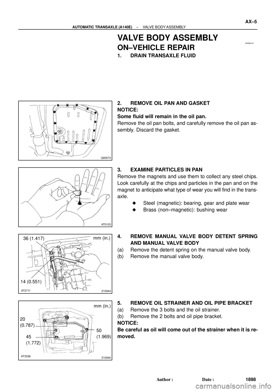
1. DRAIN TRANSAXLE FLUID
2. REMOVE OIL PAN AND GASKET
NOTICE:
Some fluid will remain in the oil pan.
Remove the oil pan bolts, and carefully remove the oil pan as-
sembly. Discard the gasket.
3. EXAMINE PARTICLES IN PAN
Remove the magnets and use them to collect any steel chips.
Look carefully at the chips and particles in the pan and on the
magnet to anticipate what type of wear you will find in the trans-
axle.
�Steel (magnetic): bearing, gear and plate wear
�Brass (non±magnetic): bushing wear
4. REMOVE MANUAL VALVE BODY DETENT SPRING
AND MANUAL VALVE BODY
(a) Remove the detent spring on the manual valve body.
(b) Remove the manual valve body.
5. REMOVE OIL STRAINER AND OIL PIPE BRACKET
(a) Remove the 3 bolts and the oil strainer.
(b) Remove the 2 bolts and oil pipe bracket.
NOTICE:
Be careful as oil will come out of the strainer when it is re-
moved.
Page 128 of 4592
AX03Q±02
AT3785
AT0103
D01019
Q05728
Connector
± AUTOMATIC TRANSAXLE (A541E)VALVE BODY ASSEMBLY
AX±7
1927 Author�: Date�:
VALVE BODY ASSEMBLY
ON±VEHICLE REPAIR
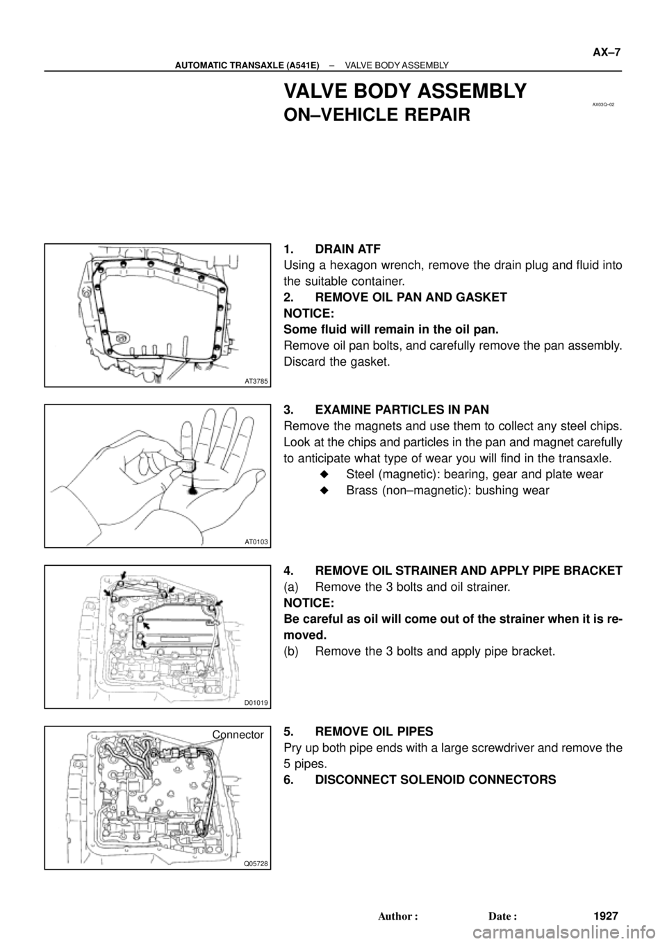
1. DRAIN ATF
Using a hexagon wrench, remove the drain plug and fluid into
the suitable container.
2. REMOVE OIL PAN AND GASKET
NOTICE:
Some fluid will remain in the oil pan.
Remove oil pan bolts, and carefully remove the pan assembly.
Discard the gasket.
3. EXAMINE PARTICLES IN PAN
Remove the magnets and use them to collect any steel chips.
Look at the chips and particles in the pan and magnet carefully
to anticipate what type of wear you will find in the transaxle.
�Steel (magnetic): bearing, gear and plate wear
�Brass (non±magnetic): bushing wear
4. REMOVE OIL STRAINER AND APPLY PIPE BRACKET
(a) Remove the 3 bolts and oil strainer.
NOTICE:
Be careful as oil will come out of the strainer when it is re-
moved.
(b) Remove the 3 bolts and apply pipe bracket.
5. REMOVE OIL PIPES
Pry up both pipe ends with a large screwdriver and remove the
5 pipes.
6. DISCONNECT SOLENOID CONNECTORS
Page 186 of 4592
AUTOMATIC TRANSAXLECOMPONENT PARTS REMOVAL ±
AX±16
(b) Remove the cover.
7. REMOVE OIL PAN AND GASKET
(a) Remove the 15 bolts.
(b) Remove the oil pan by lifting transaxle case.
NOTICE: Do not turn the transaxle over as this will contami-
nate the valve body with the foreign materials in the bottom
of the oil pan.
(c) Place the transaxle on wooden blocks to prevent damage
to the tube bracket.
8. EXAMINE PARTICLES IN PAN
Remove the magnets and use them to collect any steel
chips. Look carefully at the chips and particles in the oil
pan and on the magnets to anticipate what type of wear
you will find in the transmission:
Steel (magnetic): bearing, gear and plate wear
Brass (non±magnetic): bushing wear
9. DISCONNECT NO.1 AND NO.2 SOLENOID CONNEC-
TORS
10. REMOVE TUBE BRACKET AND OIL STRAINER
Page 320 of 4592
AUTOMATIC TRANSAXLECOMPONENT PARTS REMOVAL ±
AX±14
5. REMOVE T/M REVOLUTION SENSOR
(a) Remove the bolt and T/M revolution sensor.
(b) Remove the O±ring from the T/M revolution sensor.
6. REMOVE TRANSAXLE CASE UPPER COVER
7. REMOVE OIL PAN AND GASKET
(a) Remove the 17 bolts.
(b) Remove the oil pan by lifting transaxle case.
NOTICE: Do not turn the transaxle over as this will contami-
nate the valve body with the foreign materials in the bottom
of the oil pan.
(c) Place the transaxle on wooden blocks to prevent damage
to the oil pipe bracket.
8. EXHAUST PARTICLES IN PAN
Remove the magnet and use it to collect any steel chips.
Lock carefully at the chips and particles in the oil pan and
on magnet to anticipate what type of wear you will find in
the transaxle.
�Steel (magnetic): bearing, gear and plate wear
�Brass (non±magnetic): bushing wear
9. REMOVE OIL PIPE BRACKET AND STRAINER
Page 463 of 4592
AUTOMATIC TRANSAXLECOMPONENT PARTS REMOVAL ±
AX±14
5. REMOVE T/M REVOLUTION SENSOR
(a) Remove the bolt and T/M revolution sensor.
(b) Remove the O±ring from the T/M revolution sensor.
6. REMOVE TRANSAXLE CASE UPPER COVER
7. REMOVE OIL PAN AND GASKET
(a) Remove the 17 bolts.
(b) Remove the oil pan by lifting transaxle case.
NOTICE: Do not turn the transaxle over as this will contami-
nate the valve body with the foreign materials in the bottom
of the oil pan.
(c) Place the transaxle on wooden blocks to prevent damage
to the oil pipe bracket.
8. EXHAUST PARTICLES IN PAN
Remove the magnet and use it to collect any steel chips.
Lock carefully at the chips and particles in the oil pan and
on magnet to anticipate what type of wear you will find in
the transaxle.
�Steel (magnetic): bearing, gear and plate wear
�Brass (non±magnetic): bushing wear
9. REMOVE OIL PIPE BRACKET AND STRAINER
Page 1142 of 4592
CO067±03
Z18990
Radiator Drain Plug
Engine Drain Plug CO±2
± COOLING (5S±FE)COOLANT
1576 Author�: Date�:
REPLACEMENT
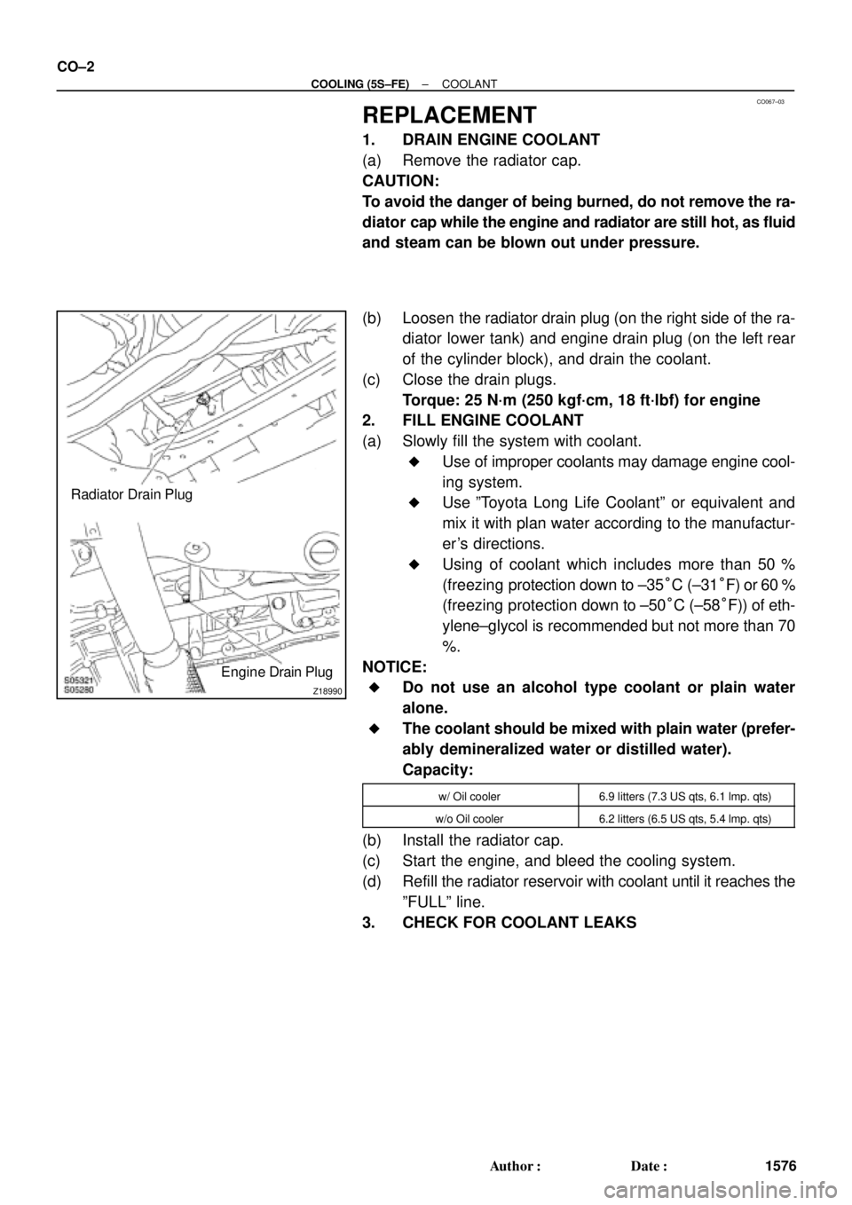
1. DRAIN ENGINE COOLANT
(a) Remove the radiator cap.
CAUTION:
To avoid the danger of being burned, do not remove the ra-
diator cap while the engine and radiator are still hot, as fluid
and steam can be blown out under pressure.
(b) Loosen the radiator drain plug (on the right side of the ra-
diator lower tank) and engine drain plug (on the left rear
of the cylinder block), and drain the coolant.
(c) Close the drain plugs.
Torque: 25 N´m (250 kgf´cm, 18 ft´lbf) for engine
2. FILL ENGINE COOLANT
(a) Slowly fill the system with coolant.
�Use of improper coolants may damage engine cool-
ing system.
�Use ºToyota Long Life Coolantº or equivalent and
mix it with plan water according to the manufactur-
er's directions.
�Using of coolant which includes more than 50 %
(freezing protection down to ±35°C (±31°F) or 60 %
(freezing protection down to ±50°C (±58°F)) of eth-
ylene±glycol is recommended but not more than 70
%.
NOTICE:
�Do not use an alcohol type coolant or plain water
alone.
�The coolant should be mixed with plain water (prefer-
ably demineralized water or distilled water).
Capacity:
w/ Oil cooler6.9 litters (7.3 US qts, 6.1 lmp. qts)
w/o Oil cooler6.2 litters (6.5 US qts, 5.4 lmp. qts)
(b) Install the radiator cap.
(c) Start the engine, and bleed the cooling system.
(d) Refill the radiator reservoir with coolant until it reaches the
ºFULLº line.
3. CHECK FOR COOLANT LEAKS
Page 1227 of 4592

± DIAGNOSTICSENGINE (5S±FE)
DI±15
250 Author�: Date�:
(b) TOYOTA Enhanced Signals.
TOYOTA hand±held tester displayMeasurement ItemNormal Condition*1
MISFIRE RPMEngine RPM for first misfire rangeMisfire 0: 0 rpm
MISFIRE LOADEngine load for first misfire rangeMisfire 0: 0 g/r
INJECTORFuel injection time for cylinder No.1Idling: 2.9 ~ 5.1 ms
IAC DUTY RATIOIntake Air Control Valve Duty Ratio
Opening ratio rotary solenoid type IAC valveIdling: 25 ~ 62 %
STARTER SIGStarter SignalCranking: ON
CTP SIGClosed Throttle Position SignalThrottle fully closed: ON
A/C SIGA/C Switch SignalA/C ON: ON
PNP SIGPark/Neutral Position Switch SignalP or N position: ON
ELECTCL LOAD SIGElectrical Load SignalDefogger S/W ON: ON
STOP LIGHT SWStop Light Switch SignalStop light switch ON: ON
PS OIL PRESS SWPower Steering Oil Pressure Switch SignalTurn steering wheel: ON
FC IDLFuel Cut Idle: Fuel cut when throttle valve fully
closed, during decelerationFuel cut operating: ON
FC TAUFuel Cut TAU: Fuel cut during very light loadFuel cut operating: ON
CYL#1, CYL#2, CYL#3, CYL#4Abnormal revolution variation for each cylinder0 %
IGNITIONTotal number of ignition for every 1,000 revolu-
tions0 ~ 2,000 rpm
EGR SYSTEMEGR system operating conditionIdling: OFF
FUEL PUMPFuel Pump SignalIdling: ON
A/C CUT SIGA/C Cut SignalA/C S/W OFF: ON
A/C MAG CLUTCHA/C Switch SignalA/C ON: ON
EVAP (PURGE) VSVEVAP VSV SignalVSV operating: Avove 30 %
VAPOR PRESS VSVVapor Pressure VSV SignalVSV operating: ON
TOTAL FT B1Total Fuel Trim Bank 1: Average value for fuel
trim system of bank 1Idling: 0.8 ~ 1.2 V
O2 LR B1, S1 *2
Heated Oxygen Sensor Lean Rich Bank 1 Sen-
sor 1: Response time for oxygen sensor output to
switch from lean to rich
Idling after warming up: 0 ~ 1,000 msec.
O2 RL B1, S1 *2
Heated Oxygen Sensor Rich Lean Bank 1 Sen-
sor 1: Response time for oxygen sensor output to
switch from rich to lean
Idling after warming up: 0 ~ 1,000 msec.
*1: If no conditions are specifically stated for ºldlingº, it means the shift lever is at N or P position, the A/C
switch is OFF and all accessory switches are OFF.
*2: Except California Specification vehicles.
Page 1305 of 4592
A00434
± DIAGNOSTICSENGINE (5S±FE)
DI±93
328 Author�: Date�:
2 Check spark plug and spark of misfiring cylinder.
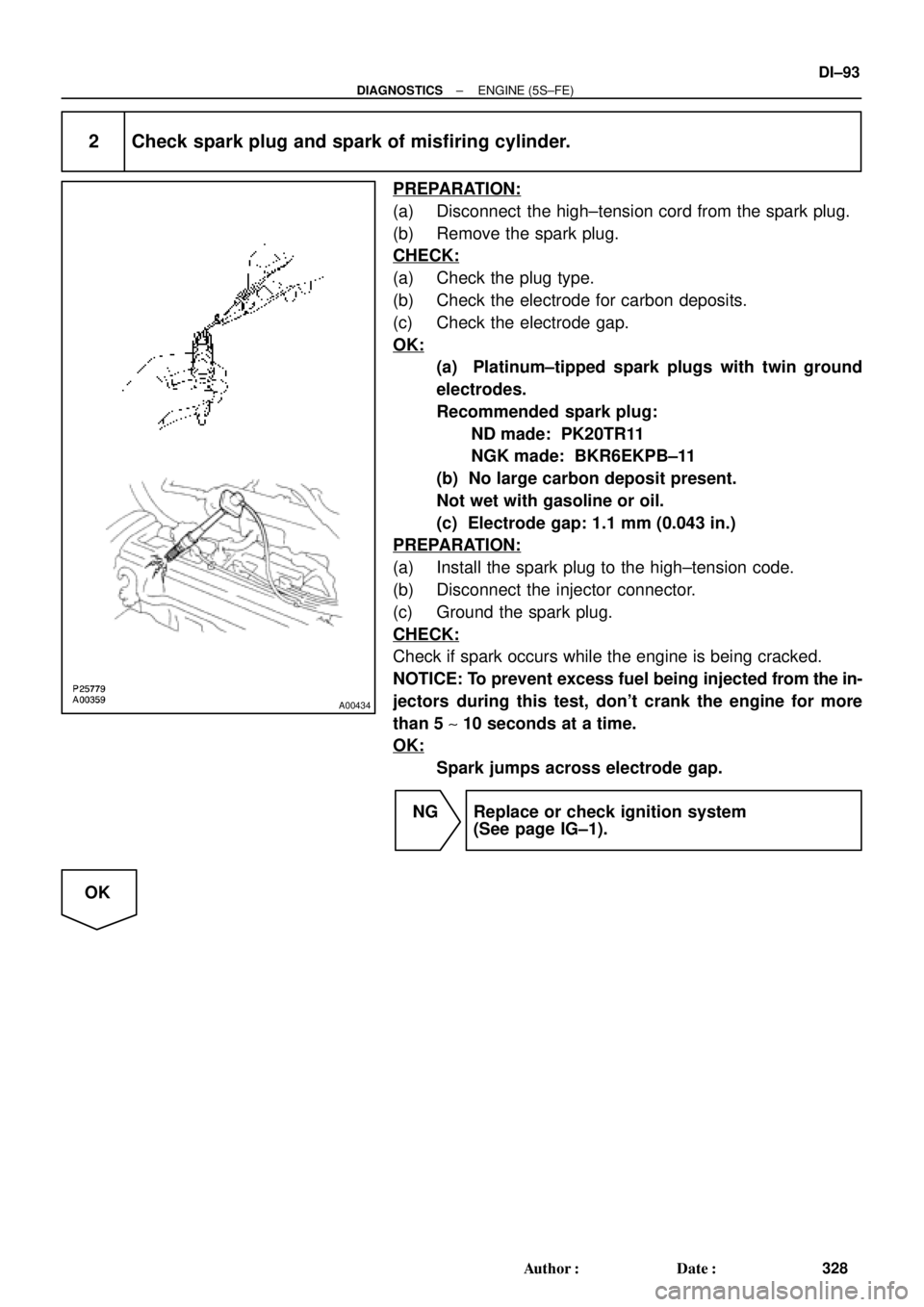
PREPARATION:
(a) Disconnect the high±tension cord from the spark plug.
(b) Remove the spark plug.
CHECK:
(a) Check the plug type.
(b) Check the electrode for carbon deposits.
(c) Check the electrode gap.
OK:
(a) Platinum±tipped spark plugs with twin ground
electrodes.
Recommended spark plug:
ND made: PK20TR11
NGK made: BKR6EKPB±11
(b) No large carbon deposit present.
Not wet with gasoline or oil.
(c) Electrode gap: 1.1 mm (0.043 in.)
PREPARATION:
(a) Install the spark plug to the high±tension code.
(b) Disconnect the injector connector.
(c) Ground the spark plug.
CHECK:
Check if spark occurs while the engine is being cracked.
NOTICE: To prevent excess fuel being injected from the in-
jectors during this test, don't crank the engine for more
than 5 ~ 10 seconds at a time.
OK:
Spark jumps across electrode gap.
NG Replace or check ignition system
(See page IG±1).
OK