Page 585 of 4592
1. Integration Relay (I/P J/B No.1)
2. Light Control Switch
3. Wire HarnessBE±1")
BE±4
± BODY ELECTRICALBODY ELECTRICAL SYSTEM
2224 Author�: Date�:
Taillight does not light.
(Headlight does not light)1. Integration Relay (I/P J/B No.1)
2. Light Control Switch
3. Wire HarnessBE±14
BE±24
±
Taillight does not light.
(Headlight is normal)
1. TAIL Fuse (I/P J/B No.1)
2. Taillight Control Relay (I/P J/B No.1)
3. Integration Relay (I/P J/B No.1)
4. Light Control Switch
5. Wire Harness±
BE±24
BE±14
BE±24
±
Only one side light does not light.1. Bulb
2. Wire Harness±
±
Rear Combination light does not light.
1. Bulb
2. Light Failure Sensor
3. Wire Harness±
BE±37
±
ºAuto Turn±off Systemº does not operate.
1. GAUGE Fuse (I/P J/B No.1)
2. Integration Relay (I/P J/B No.1)
3. Door Courtesy Switch (Driver's)
4. Wire Harness±
BE±14
BE±24
±
*Terminal L of generator and parking brake switch
TURN SIGNAL AND HAZARD WARNING SYSTEM
SymptomSuspect AreaSee page
ºHazardº and ºTurnº do not light up.
1. Hazard Warning Switch
2. Turn Signal Flasher
3. Wire HarnessBE±30
BE±30
±
The flashing frequency is abnormal.
1. Bulb
2. Turn Signal Switch
3. Wire Harness±
BE±30
±
Hazard warning light does not light up.
(Turn is normal.)1. HORN Fuse (E/G Room J/B No.2)
2. Wire Harness±
±
Hazard warning light does not light up in one direction.1. Hazard Warning Switch
2. Wire HarnessBE±30
±
*1Turn signal does not light up.
1. Ignition Switch
2. TURN Fuse (I/P J/B No.1)
3. Turn Signal Switch
4. Wire HarnessBE±14
±
BE±30
±
*2Turn signal does not light up.
1. TURN Fuse (I/P J/B No.1)
2. Turn Signal Switch
3. Wire Harness±
BE±30
±
Turn signal does not light up in one direction.1. Turn Signal Switch
2. Wire HarnessBE±30
±
Only one bulb does not light up.1. Bulb
2. Wire Harness±
±
*1: Combination meter, wiper and washer do not operate.
*
2: Combination meter, wiper and washer are normal.
INTERIOR LIGHT SYSTEM
SymptomSuspect AreaSee page
ºIlluminated Entry Systemº does not operate.
1. Door Courtesy Switch
2. Integration Relay (I/P J/B No.1)
3. Wire HarnessBE±32
BE±14
±
Only one interior light does not light up.1. Bulb
2. Wire Harness±
±
Interior light does not light up (All).1. DOME Fuse (E/G Room J/B No.2)
2. Wire Harness±
±
Page 586 of 4592

± BODY ELECTRICALBODY ELECTRICAL SYSTEM
BE±5
2225 Author�: Date�:
Dome light does not light up.
1. Bulb
2. Dome Light
3. Wire Harness±
BE±32
±
Map Light does not light up.
1. Bulb
2. Map Light
3. Wire Harness±
BE±32
±
Luggage compartment light does not light up.
1. Bulb
2. Luggage compartment door courtesy switch
3. Wire Harness±
BE±32
±
BACK±UP LIGHT SYSTEM
SymptomSuspect AreaSee page
Back±Up Light does not light up.
1. GAUGE Fuse (I/P J/B No.1)
2. Ignition Switch
3. Wire Harness
4. Bulb±
BE±14
±
±
Back±Up Light remains always ON.
1. Back±Up Light Switch (M/T)
2. Park/Neutral Position Switch (A/T) (A140E)
(A541E)
3. Wire HarnessBE±35
DI±424
DI±479
±
Only one light does not light up.1. Bulb
2. Wire Harness±
±
STOP LIGHT SYSTEM
SymptomSuspect AreaSee page
Stop light does not light up.
1. STOP Fuse (I/P J/B No.1)
2. Stop Light Switch
3. Wire Harness±
BE±37
±
Only one light always lights up.1. Wire Harness±
Only one light does not light.1. Bulb
2. Wire Harness±
±
WIPER AND WASHER SYSTEM
*
1: Inspect wiper arm and blade set position
SymptomSuspect AreaSee page
Wiper and washers do not operate.
1. WIPER Fuse (I/P J/B No.1)
2. Wiper Switch
3. Wiper Motor
4. Wire Harness±
BE±40
BE±40
±
Wipers do not operate in LO or HI.
1. Wiper Switch
2. Wiper Motor
3. Wire HarnessBE±40
BE±40
±
Wipers do not operate in INT.
1. Wiper Switch
2. Wiper Motor
3. Wire HarnessBE±40
BE±40
±
Washer motor does not operate.
1. Washer Switch
2. Washer Motor
3. Wire HarnessBE±40
BE±40
±
Wipers do not operate when washer switch in ON.1. Washer Motor
2. Wire HarnessBE±40
±
Page 587 of 4592

BE±6
± BODY ELECTRICALBODY ELECTRICAL SYSTEM
2226 Author�: Date�:
Washer fluid does not operate.1. Washer Hose and Nozzle±
� In wiper switch HI position, the wiper blade is in contact with
the body.
� When the wiper switch is OFF, the wiper blade does not
retract or the retract position is wrong.1. *1Wiper Switch
2. Wire HarnessBE±40
±
COMBINATION METER
METER, GAUGES AND ILLUMINATION:
SymptomSuspect AreaSee page
Tachometer, Fuel Gauge and Engine Coolant Temperature Gauge
do not operate.1. GAUGE Fuse (I/P J/B No.1)
2. Meter Circuit Plate
3. Wire Harness±
BE±46
±
Speedometer does not operate.
1. No.1 Vehicle Speed Sensor
2. Meter Circuit Plate
3. Wire HarnessBE±47
BE±46
±
Tachometer does not operate.
1. Igniter (5S±FE)
(1MZ±FE)
2. Meter Circuit Plate
3. Wire HarnessIG±1
IG±1
BE±46
±
Fuel Gauge does not operate or abnormal operation.
1. Fuel Receiver Gauge
2. Fuel Sender Gauge
3. Meter Circuit Plate
4. Wire HarnessBE±47
BE±47
BE±46
±
Engine Coolant Temperature Gauge does not operate or abnormal
operation
1. Engine Coolant Temperature Receiver Gauge
2. Engine Coolant Temperature Sender Gauge
3. Meter Circuit Plate
4. Wire HarnessBE±47
BE±47
BE±46
±
All illumination lights do not light up.
1. TAIL Fuse (I/P J/B No.1)
2. Light Control Rheostat
3. Wire Harness±
BE±47
±
Brightness does not change even when rheostat turned.1. Bulb
2. Wire Harness±
±
Only one illumination light does not light up.1. Bulb
2. Wire Harness±
±
COMBINATION METER
WARNING LIGHTS:
SymptomSuspect AreaSee page
Warning lights do not light up. (Except Discharge, Open Door and
SRS)1. GAUGE Fuse (I/P J/B No.1)
2. Meter Circuit Plate
3. Wire Harness±
BE±46
±
Low Oil Pressure warning light does not light up.
1. Bulb
2. Low Oil Pressure Warning Switch
3. Meter Circuit Plate
4. Wire Harness±
BE±47
BE±46
±
Fuel Level warning light does not light up.
1. Bulb
2. Fuel Level Warning Switch
3. Meter Circuit Plate
4. Wire Harness±
BE±47
BE±46
±
ABS warning light does not light up.
1. Bulb
2. ABS ECU
3. Wire Harness±
IN±31
±
Page 604 of 4592
BE0A5±02
N18012
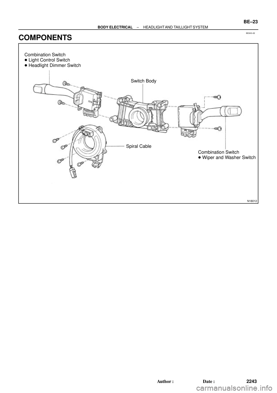
Combination Switch
� Light Control Switch
� Headlight Dimmer Switch
Switch Body
Combination Switch
� Wiper and Washer Switch Spiral Cable
± BODY ELECTRICALHEADLIGHT AND TAILLIGHT SYSTEM
BE±23
2243 Author�: Date�:
COMPONENTS
Page 620 of 4592
BE0AG±03
Z19049
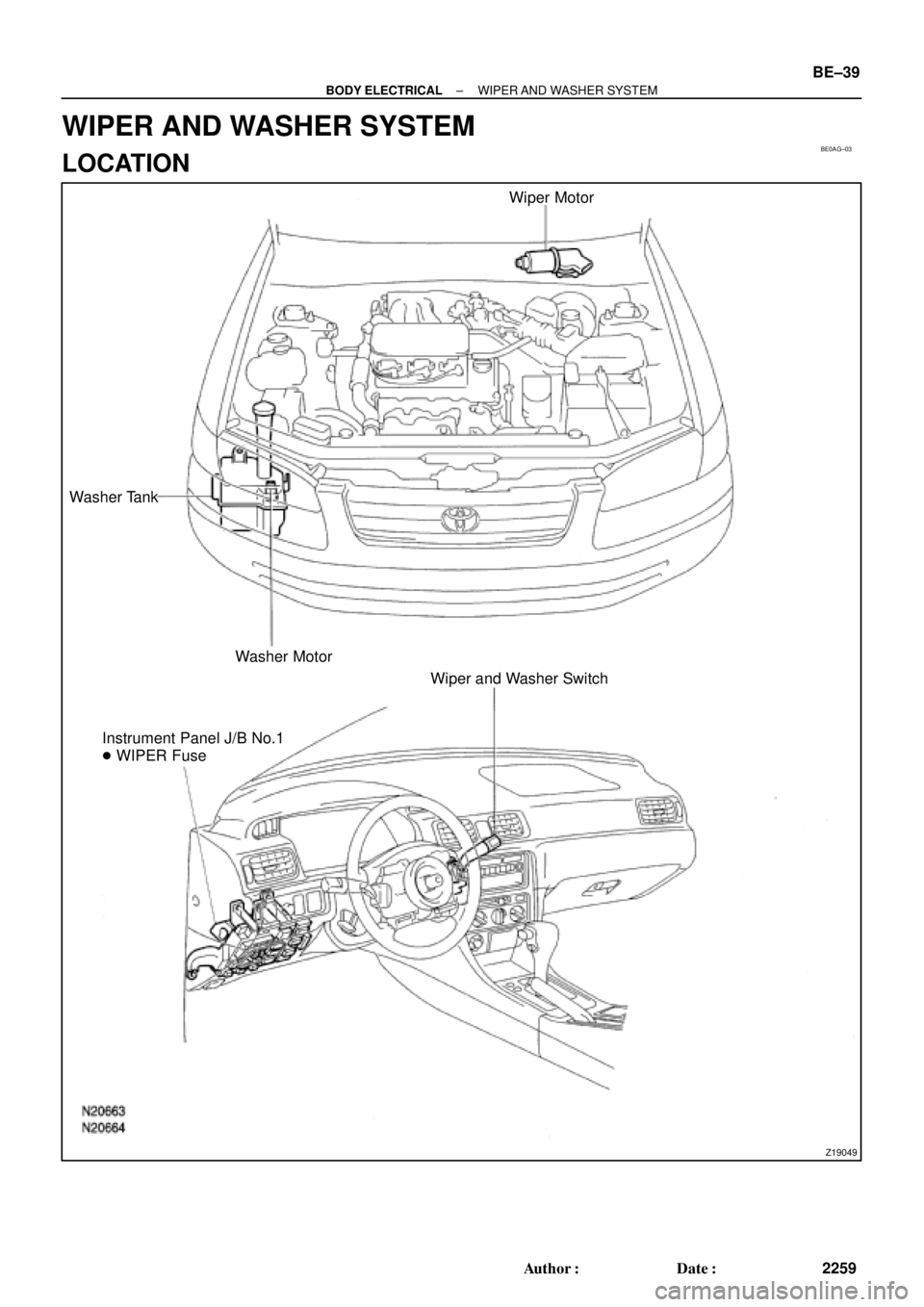
Wiper Motor
Washer Tank
Washer Motor
Wiper and Washer Switch
Instrument Panel J/B No.1
� WIPER Fuse
± BODY ELECTRICALWIPER AND WASHER SYSTEM
BE±39
2259 Author�: Date�:
WIPER AND WASHER SYSTEM
LOCATION
Page 621 of 4592

BE0AH±03
N20218
w/o Timer
w/ TimerWasher ON
Washer ONOFF
INT
LO
HI
OFF
INT
LO
HI
2 7
8
17
1611
N20210
2
7
16
N20211
2 7
16 17
INT time control
switch position
FAST
SLOW
Non variable typeVoltage
Approx. 2 sec.
Battery positive voltage
0 V
Battery positive voltage
0 V
Battery positive voltage
0 V 10.7 ± 5 sec.
3.3 ± 1 sec.
BE±40
± BODY ELECTRICALWIPER AND WASHER SYSTEM
2260 Author�: Date�:
INSPECTION
1. INSPECT FRONT WIPER AND WASHER SWITCH
CONTINUITY
Switch positionTester connectionSpecified condition
OFF7 ± 16Continuity
INT7 ± 16Continuity
LO7 ± 17Continuity
HI8 ± 17Continuity
Washer ON2 ± 11Continuity
If continuity is not as specified, replace the switch.
2. INSPECT INTERMITTENT OPERATION
(a) Turn the wiper switch to INT position.
(b) Turn the intermittent time control switch to FAST position.
(c) Connect the positive (+) lead from the battery to terminal
16 and the negative (±) lead to terminal 2.
(d) Connect the positive (+) lead from the voltmeter to termi-
nal 7 and the negative (±) lead to terminal 2, check that
the meter needle indicates battery positive voltage.
(e) After connecting terminal 16 to terminal 17, connect it to
terminal 2, check the voltage rises from 0 volts to battery
positive voltage within the time, as shown in the table.
If operation is not as specified, replace the wiper and washer
switch.
Page 622 of 4592
N20210
2
7
16
N11301
Washer Switch ON
OFF
Battery positive
Voltage
0 VLess than 1 sec.Approx. 3 sec.
N20151
4
5
± BODY ELECTRICALWIPER AND WASHER SYSTEM
BE±41
2261 Author�: Date�:
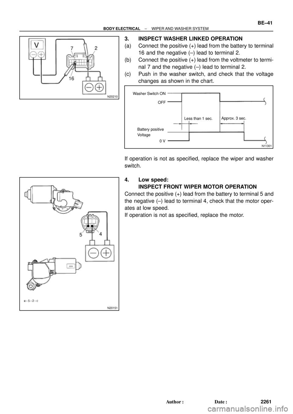
3. INSPECT WASHER LINKED OPERATION
(a) Connect the positive (+) lead from the battery to terminal
16 and the negative (±) lead to terminal 2.
(b) Connect the positive (+) lead from the voltmeter to termi-
nal 7 and the negative (±) lead to terminal 2.
(c) Push in the washer switch, and check that the voltage
changes as shown in the chart.
If operation is not as specified, replace the wiper and washer
switch.
4. Low speed:
INSPECT FRONT WIPER MOTOR OPERATION
Connect the positive (+) lead from the battery to terminal 5 and
the negative (±) lead to terminal 4, check that the motor oper-
ates at low speed.
If operation is not as specified, replace the motor.
Page 623 of 4592
N20152
3
4
N20153
5
4 BE±42
± BODY ELECTRICALWIPER AND WASHER SYSTEM
2262 Author�: Date�:
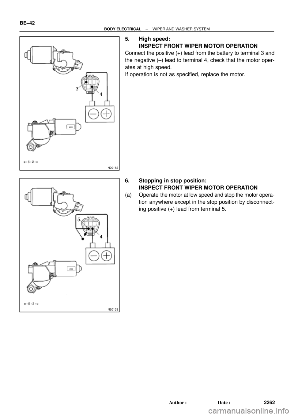
5. High speed:
INSPECT FRONT WIPER MOTOR OPERATION
Connect the positive (+) lead from the battery to terminal 3 and
the negative (±) lead to terminal 4, check that the motor oper-
ates at high speed.
If operation is not as specified, replace the motor.
6. Stopping in stop position:
INSPECT FRONT WIPER MOTOR OPERATION
(a) Operate the motor at low speed and stop the motor opera-
tion anywhere except in the stop position by disconnect-
ing positive (+) lead from terminal 5.