Page 1 of 4592

AC2810
AC0LG±02
AC2811
N11084
Wrong Okey
HI LO HILO
± AIR CONDITIONINGAIR CONDITIONING SYSTEM
AC±1
2483 Author�: Date�:
AIR CONDITIONING SYSTEM
PRECAUTION
1. DO NOT HANDLE REFRIGERANT IN AN ENCLOSED
AREA OR WEAR EYE PROTECTION
2. ALWAYS WEAR EYE PROTECTION
3. BE CAREFUL NOT TO GET LIQUID REFRIGERANT IN
YOUR EYES OR ON YOUR SKIN
If liquid refrigerant gets in your eyes or on your skin.
(a) Wash the area with lots of cool water.
CAUTION:
Do not rub your eyes or skin.
(b) Apply clean petroleum jelly to the skin.
(c) Go immediately to a physician or hospital for professional
treatment.
4. NEVER HEAT CONTAINER OR EXPOSE IT TO NAKED
FLAME
5. BE CAREFUL NOT TO DROP CONTAINER AND NOT
TO APPLY PHYSICAL SHOCKS TO IT
6. DO NOT OPERATE COMPRESSOR WITHOUT
ENOUGH REFRIGERANT IN REFRIGERATION SYS-
TEM
If there is not enough refrigerant in the refrigerant system oil lu-
brication will be insufficient and compressor burnout may occur,
so that care to avoid this, necessary care should be taken.
7. DO NOT OPEN PRESSURE MANIFOLD VALVE WHILE
COMPRESSOR IS OPERATE
If the high pressure valve is opened, refrigerant flows in the re-
verse direction and could cause the charging cylinder to rup-
ture, so open and close the only low pressure valve.
8. BE CAREFUL NOT TO OVERCHARGE SYSTEM WITH
REFRIGERANT
If refrigerant is overcharged, it causes problems such as insuffi-
cient cooling, poor fuel economy, engine overheating etc.
Page 7 of 4592

I01390
Condition: Insufficient cooling
I01392
Condition: Insufficient cooling
NOTE : These gauge indica-
tions are shown when the
refrigeration system has
been opened and the refrig-
erant charged without vacu-
um purging.
± AIR CONDITIONINGAIR CONDITIONING SYSTEM
AC±7
2489 Author�: Date�:
(6) Refrigerant overcharged or insufficient cooling of
condenser
Symptom seen in
refrigeration systemProbable causeDiagnosisRemedy
� Pressure too high on both low
and high pressure sides
� No air bubbles seen through the
sight glass even when the engine
rpm is lowered� Unable to develop sufficient per-
formance due to excessive refrig-
eration system
� Insufficient cooling of condenser� Excessive refrigerant in
cycle " refrigerant over charged
� Condenser cooling " condenser
fins clogged of condenser fan
faulty
(1) Clean condenser
(2) Check condenser fan motor
operation
(3) If (1) and (2) are in normal
state, check amount of refrigerant
Charge proper amount of refriger-
ant
(7) Air present in refrigeration system
Symptom seen in
refrigeration systemProbable causeDiagnosisRemedy
� Pressure too high on both low
and high pressure sides
� The low pressure piping hot to
touch
� Bubbles seen in sight glass
Air entered in refrigeration system
� Air present in refrigeration sys-
tem
� Insufficient vacuum purging
(1) Check compressor oil to see if
it is dirty or insufficient
(2) Evacuate air and charge new
refrigerant
Page 69 of 4592
AC0N3±02
N20292
AC±68
± AIR CONDITIONINGPRESSURE SWITCH
2550 Author�: Date�:
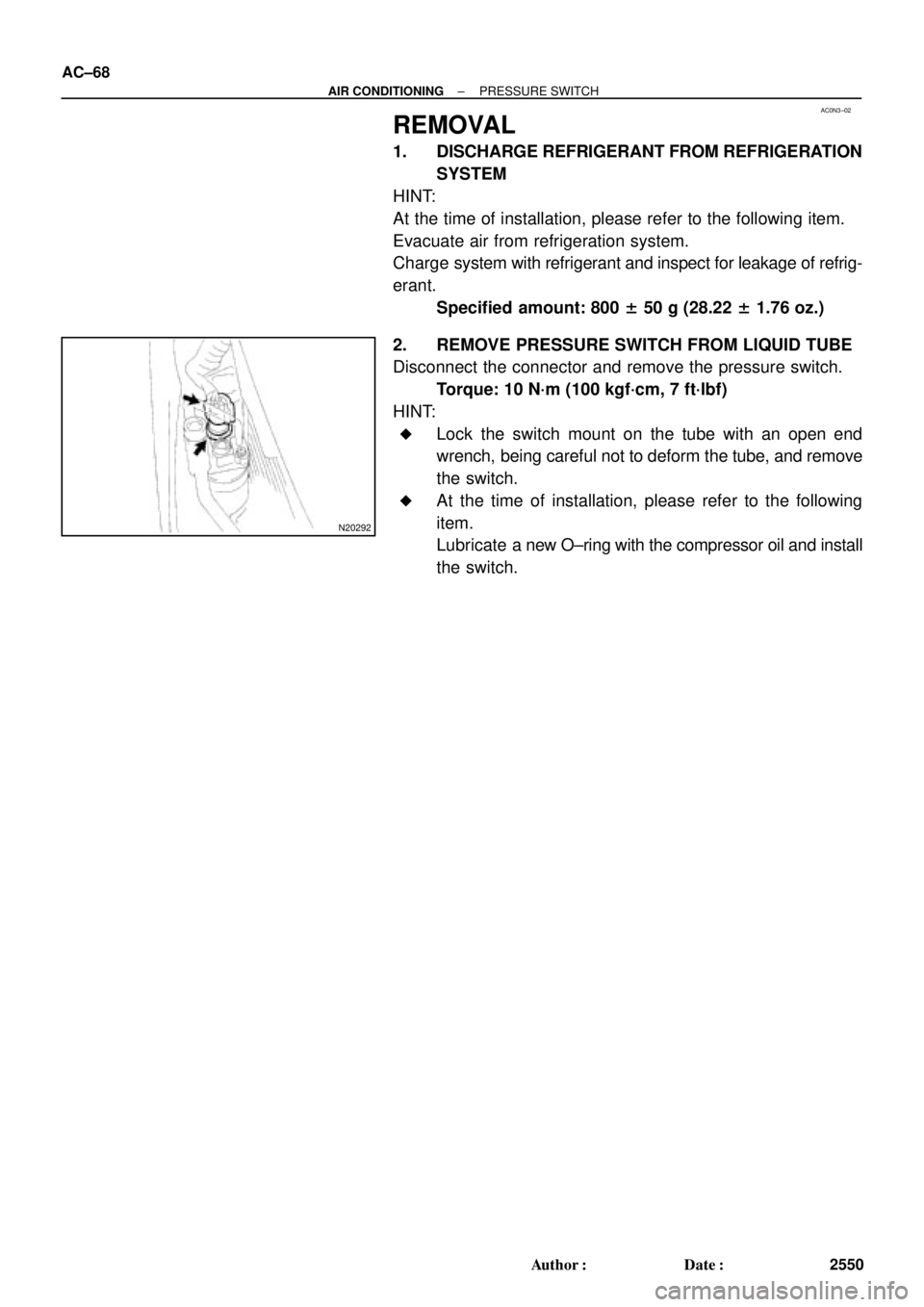
REMOVAL
1. DISCHARGE REFRIGERANT FROM REFRIGERATION
SYSTEM
HINT:
At the time of installation, please refer to the following item.
Evacuate air from refrigeration system.
Charge system with refrigerant and inspect for leakage of refrig-
erant.
Specified amount: 800 ± 50 g (28.22 ± 1.76 oz.)
2. REMOVE PRESSURE SWITCH FROM LIQUID TUBE
Disconnect the connector and remove the pressure switch.
Torque: 10 N´m (100 kgf´cm, 7 ft´lbf)
HINT:
�Lock the switch mount on the tube with an open end
wrench, being careful not to deform the tube, and remove
the switch.
�At the time of installation, please refer to the following
item.
Lubricate a new O±ring with the compressor oil and install
the switch.
Page 166 of 4592
Total No. of coils and Color
Upper valve body
Throttle modulator valve21.7")
AUTOMATIC TRANSAXLESERVICE SPECIFICATIONS ±
AX±14
Valve Body Spring
SpringFree length and Coil outer
diameter mm (in.)Total No. of coils and Color
Upper valve body
Throttle modulator valve21.7 (0.854)
9.5 (0.374)9.5
None
Accumulator control valve28.1 (0.105)
10.6 (0.417)13.0
Yellow
Low coast modulator valve21.6 (0.850)
7.9 (0.311)11.5
None
Down shift plug29.8 (1.172)
8.7 (0.344)13.5
Yellow
Throttle valve30.7 (1.209)
9.2 (0.362)9.5
None
Second coast modulator valve20.9 (0.824)
8.5 (0.336)10.0
Light Green
Cut±back valve21.8 (0.858)
6.0 (0.236)13.5
None
Lock±up relay valve26.6 (1.046)
10.2 (0.402)11.5
Green
Lower valve body
Pressure relief valve11.2 (0.441)
6.4 (0.252)7.5
None
1 ± 2 shift valve29.3 (1.152)
9.7 (0.382)10.5
None
2 ± 3 shift valve29.3 (1.152)
9.7 (0.382)10.5
None
3 ± 4 shift valve29.3 (1.152)
9.7 (0.382)10.5
None
Primary regulator valve66.7 (2.453)
18.6 (0.732)12.5
None
Secondary regulator valve43.6 (1.717)
10.9 (0.429)11.5
None
Lock±up signal valve30.0 (1.181)
8.2 (0.323)11.5
None
Cooler By±pass valve19.9 (0.784)
11.0 (0.433)8.5
None
Valve Body Retainer
ReteinerHeight
mm (in.)Width
mm (in.)Thickness
mm (in.)
Upper valve body
Throttle Modulator valve9.2 (0.362)5.0 (0.197)3.2 (0.126)
Accumulator control valve11.5 (0.453)5.0 (0.197)3.2 (0.126)
Cut±back valve9.2 (0.591)5.0 (0.197)3.2 (0.126)
Lock±up relay valve15.0 (0.591)5.0 (0.197)3.2 (0.126)
Second coast modulator valve15.0 (0.591)5.0 (0.197)3.2 (0.126)
Lower valve body
Primary regulator valve9.2 (0.362)5.0 (0.197)3.2 (0.126)
Page 385 of 4592
AUTOMATIC TRANSAXLEVALVE BODY ±
AX±79
7. REMOVE OIL STRAINER, NO.1 LOWER VALVE BODY
COVER GASKETS AND CHECK VALVE
(a) Remove the 2 gaskets and plate from the lower valve
body.
(b) Remove the oil strainer, check valve and spring.
8. REMOVE PRESSURE RELIEF VALVE
9. REMOVE NO.2 LOWER VALVE BODY COVER, OIL
STRAINER, CHECK BALLS AND VIBRATING STOP-
PER
Remove the 11 bolts and lower valve body cover.
(b) Remove the 2 check balls, oil strainer and vibrating stop-
per.
Page 390 of 4592
AUTOMATIC TRANSAXLEVALVE BODY ±
AX±84
10. INSTALL LOWER VALVE BODY COVER GASKETS
AND NO.2 PLATE
Position a new gasket and plate and then another new
gasket.
HINT: Both gaskets are identical.
11. INSTALL LOWER VALVE BODY COVER
(a) Position the lower valve body cover.
(b) Install and finger tighten the 5 bolts.
HINT: Each bolt length is indicated below.
Bolt length
Bolt A: 47 mm (1.850 in.)
Bolt B: 14 mm (0.551 in.)
12. INSTALL PRESSURE RELIEF VALVE
13. TIGHTEN BOLTS OF UPPER AND LOWER VALVE BO-
DIES
(a) Tighten the 16 bolts in the lower valve body.
Torque: 6.6 N´m (67 kgf´cm, 58 in.´lbf)
(b) Tighten the 3 bolts in the upper valve body.
Torque: 6.6 N´m (67 kgf´cm, 58 in.´lbf)
14. INSTALL B0 ACCUMULATOR ASSEMBLY
(a) Coat new O±rings with ATF and install them to the piston.
(b) Install the spring and piston into the cylinder.
Spring dimensions
mm (in.)
ColorFree lengthCoil outer diameter
Inner White47.5 (1.870)18.9 (0.744)
Outer None16.3 (0.642)20.7 (0.815)
Page 528 of 4592
AUTOMATIC TRANSAXLEVALVE BODY ±
AX±79
7. REMOVE OIL STRAINER, NO.1 LOWER VALVE BODY
COVER GASKETS AND CHECK VALVE
(a) Remove the 2 gaskets and plate from the lower valve
body.
(b) Remove the oil strainer, check valve and spring.
8. REMOVE PRESSURE RELIEF VALVE
9. REMOVE NO.2 LOWER VALVE BODY COVER, OIL
STRAINER, CHECK BALLS AND VIBRATING STOP-
PER
Remove the 11 bolts and lower valve body cover.
(b) Remove the 2 check balls, oil strainer and vibrating stop-
per.
Page 533 of 4592
AUTOMATIC TRANSAXLEVALVE BODY ±
AX±84
10. INSTALL LOWER VALVE BODY COVER GASKETS
AND NO.2 PLATE
Position a new gasket and plate and then another new
gasket.
HINT: Both gaskets are identical.
11. INSTALL LOWER VALVE BODY COVER
(a) Position the lower valve body cover.
(b) Install and finger tighten the 5 bolts.
HINT: Each bolt length is indicated below.
Bolt length
Bolt A: 47 mm (1.850 in.)
Bolt B: 14 mm (0.551 in.)
12. INSTALL PRESSURE RELIEF VALVE
13. TIGHTEN BOLTS OF UPPER AND LOWER VALVE BO-
DIES
(a) Tighten the 16 bolts in the lower valve body.
Torque: 6.6 N´m (67 kgf´cm, 58 in.´lbf)
(b) Tighten the 3 bolts in the upper valve body.
Torque: 6.6 N´m (67 kgf´cm, 58 in.´lbf)
14. INSTALL B0 ACCUMULATOR ASSEMBLY
(a) Coat new O±rings with ATF and install them to the piston.
(b) Install the spring and piston into the cylinder.
Spring dimensions
mm (in.)
ColorFree lengthCoil outer diameter
Inner White47.5 (1.870)18.9 (0.744)
Outer None16.3 (0.642)20.7 (0.815)
 Remove the 2 gaskets and plate from the lower valve
body.
(b) Remove the oil str")

 Remove the 2 gaskets and plate from the lower valve
body.
(b) Remove the oil str")
