Page 96 of 4592
AX035±01
D00989
O/D Direct
Clutch (C
0)O/D Brake (B0) 1st & Reverse Brake (B
3)
One ± Way clutch
No.2 (F
2)2nd Brake (B
2)
Forward
Clutch (C
1)2nd Coast brake (B
1)
Direct Clutch (C
2)
O/D One ± Way
Clutch (F
0)
O/D Planetary GearCounter
Drive Gear
Intermediate
ShaftRear
Planetary Gear One Way Clutch
No.1 (F1)
Front Planetary
GearInput Shaft
Shift lever
positionGear position
Parking
Reverse
Neutral P
R
NC
1B2B3F0C0C2B0B1F1F2
D
2
L1st
2nd
3rd
O/D
1st
2nd
*3rd
1st
*2nd� �
�
� �
�
� �
�
�
�� �
�
�
� �
�
�
��
�
��
��
�� ��� � � �
��
�
��� � �
�
�� �
�
�
� Planetary Gear Unit
�: Operating
*: Down±shift only in the 3rd gear for the 2 position and 2nd gear for the L position no up±shift. AX±2
± AUTOMATIC TRANSAXLE (A140E)AUTOMATIC TRANSAXLE SYSTEM
1895 Author�: Date�:
OPERATION
Page 123 of 4592
AX03M±01
D01018
O/D Direct Clutch (C0)2nd Brake (B2)
Forward Clutch
(C
1) O/D Brake (B
0)2nd Coast Brake
(B
1)
Intermediate Shaft1st and Reverse
Brake (B3)
One±Way Clutch
No.2 (F
2) Planetary Gear Unit
O/D Planetary GearCounter Drive
Gear
Front Planetary Gear Rear Planetary GearOne±Way Clutch
No.1 (F
1)
Input ShaftDirect Clutch
(C
2)
O/D One±Way Clutch
(F
0)
P
R
N
L2 Shift Lever
Position
DGear Position
Parking
Reverse
Neutral
1st
2nd
3rd
O/D
1st
2nd
*3rd
1st
*2ndC
0C1C2B0F0F1F2B1B3B2
*Down±shift only ± no up±shift
: Operating
AX±2
± AUTOMATIC TRANSAXLE (A541E)AUTOMATIC TRANSAXLE SYSTEM
1922 Author�: Date�:
OPERATION
Page 196 of 4592
AUTOMATIC TRANSAXLECOMPONENT PARTS REMOVAL ±
AX±26
52. REMOVE FIRST AND REVERSE BRAKE PISTON
(a) Apply compressed air into the passage of the case to re-
move the piston.
HINT: Hold the piston so it is not slanted and blow with the
gun slightly away from the oil hole.
(b) If the piston does not pop out with compressed air, use
needle±nose pliers to remove it.
(c) Remove the 2 O±rings from the piston.
53. REMOVE PARKING LOCK PAWL BRACKET
54. REMOVE PARKING LOCK ROD
Page 278 of 4592
AUTOMATIC TRANSAXLECOMPONENT PARTS INSTALLATION ±
AX±108
3. INSTALL PARKING LOCK ROD
4. INSTALL PARKING LOCK PAWL BRACKET
Torque: 7.4 N´m (75 kgf´cm, 65 in.´lbf)
5. CHECK OPERATION OF PARKING LOCK PAWL
Make sure the counter driven gear is locked when the
manual valve lever is in the P position.
6. INSTALL FIRST AND REVERSE BRAKE PISTON TO
TRANSMISSION CASE
(a) Coat a new O±rings with ATF.
(b) Install the 2 O±rings on the piston.
(c) Push the piston into the bore of the case, facing the spring
seat upward.
Page 585 of 4592

BE±4
± BODY ELECTRICALBODY ELECTRICAL SYSTEM
2224 Author�: Date�:
Taillight does not light.
(Headlight does not light)1. Integration Relay (I/P J/B No.1)
2. Light Control Switch
3. Wire HarnessBE±14
BE±24
±
Taillight does not light.
(Headlight is normal)
1. TAIL Fuse (I/P J/B No.1)
2. Taillight Control Relay (I/P J/B No.1)
3. Integration Relay (I/P J/B No.1)
4. Light Control Switch
5. Wire Harness±
BE±24
BE±14
BE±24
±
Only one side light does not light.1. Bulb
2. Wire Harness±
±
Rear Combination light does not light.
1. Bulb
2. Light Failure Sensor
3. Wire Harness±
BE±37
±
ºAuto Turn±off Systemº does not operate.
1. GAUGE Fuse (I/P J/B No.1)
2. Integration Relay (I/P J/B No.1)
3. Door Courtesy Switch (Driver's)
4. Wire Harness±
BE±14
BE±24
±
*Terminal L of generator and parking brake switch
TURN SIGNAL AND HAZARD WARNING SYSTEM
SymptomSuspect AreaSee page
ºHazardº and ºTurnº do not light up.
1. Hazard Warning Switch
2. Turn Signal Flasher
3. Wire HarnessBE±30
BE±30
±
The flashing frequency is abnormal.
1. Bulb
2. Turn Signal Switch
3. Wire Harness±
BE±30
±
Hazard warning light does not light up.
(Turn is normal.)1. HORN Fuse (E/G Room J/B No.2)
2. Wire Harness±
±
Hazard warning light does not light up in one direction.1. Hazard Warning Switch
2. Wire HarnessBE±30
±
*1Turn signal does not light up.
1. Ignition Switch
2. TURN Fuse (I/P J/B No.1)
3. Turn Signal Switch
4. Wire HarnessBE±14
±
BE±30
±
*2Turn signal does not light up.
1. TURN Fuse (I/P J/B No.1)
2. Turn Signal Switch
3. Wire Harness±
BE±30
±
Turn signal does not light up in one direction.1. Turn Signal Switch
2. Wire HarnessBE±30
±
Only one bulb does not light up.1. Bulb
2. Wire Harness±
±
*1: Combination meter, wiper and washer do not operate.
*
2: Combination meter, wiper and washer are normal.
INTERIOR LIGHT SYSTEM
SymptomSuspect AreaSee page
ºIlluminated Entry Systemº does not operate.
1. Door Courtesy Switch
2. Integration Relay (I/P J/B No.1)
3. Wire HarnessBE±32
BE±14
±
Only one interior light does not light up.1. Bulb
2. Wire Harness±
±
Interior light does not light up (All).1. DOME Fuse (E/G Room J/B No.2)
2. Wire Harness±
±
Page 588 of 4592

± BODY ELECTRICALBODY ELECTRICAL SYSTEM
BE±7
2227 Author�: Date�:
Seat Belt warning light does not light up.
1. Bulb
2. Seat Belt Buckle Switch
3. Integration Relay (I/P J/B No.1)
4. Wire Harness±
BE±47
BE±47
±
Discharge warning light does not light up.
1. IGN Fuse (I/P J/B No.1)
2. Bulb
3. Wire Harness
4. Generator (5S±FE)
(1MZ±FE)±
±
±
CH±1
CH±1
Light Failure warning light does not light up.
1. Bulb
2. Light Failure Sensor
3. Bulb Check Relay
4. Wire Harness
5. Taillight system±
BE±37
BE±47
±
BE±24
Brake warning light does not light up.
1. Bulb
2. Parking Brake Switch
3. Brake Fluid Level Warning Switch
4. Bulb Check Relay
5. Meter Circuit Plate
6. Wire Harness±
BE±47
BE±47
BE±47
BE±46
±
SRS Warning light does not light up.
1. ECU±B Fuse (E/G Room J/B No.2)
2. Bulb
3. Airbag Sensor Assembly
4. Meter Circuit Plate
5. Wire Harness±
±
DI±626
BE±46
±
Open Door warning light does not light up.
1. DOME Fuse (E/G Room J/B No.2)
2. Bulb
3. Door Courtesy Switch
4. Meter Circuit Plate
5. Wire Harness±
±
BE±32
BE±46
±
Washer Level warning light does not light up.
1. Bulb
2. Washer Fluid Level Warning Switch
3. Meter Circuit Plate
4. Wire Harness±
BE±47
BE±46
±
COMBINATION METER
INDICATOR LIGHTS:
SymptomSuspect AreaSee page
O/D OFF indicator light does not light up.
1. Bulb
2. O/D OFF Switch (A140E)
(A541E)
3. Meter Circuit Plate
4. Wire Harness±
DI±431
DI±487
BE±46
±
Cruise Control indicator light does not light up.
1. Bulb
2. Cruise Control ECU
3. Meter Circuit Plate
4. Wire Harness±
IN±31
BE±46
±
High beam indicator light does not light up.
1. Bulb
2. Meter Circuit Plate
3. Wire Harness
4. Headlight System±
BE±46
±
BE±22
Turn indicator light does not light up.
1. Bulb
2. Meter Circuit Plate
3. Wire Harness
4. Turn Signal and Hazard Warning System±
BE±46
±
BE±29
Page 606 of 4592

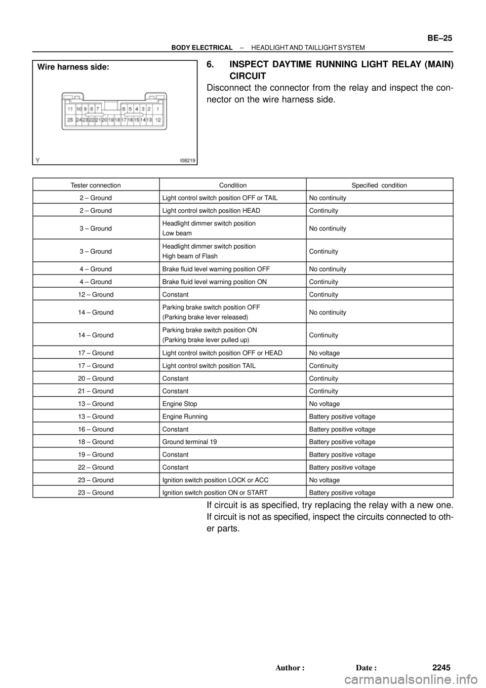
I08219
Wire harness side:
± BODY ELECTRICALHEADLIGHT AND TAILLIGHT SYSTEM
BE±25
2245 Author�: Date�:
6. INSPECT DAYTIME RUNNING LIGHT RELAY (MAIN)
CIRCUIT
Disconnect the connector from the relay and inspect the con-
nector on the wire harness side.
Tester connectionConditionSpecified condition
2 ± GroundLight control switch position OFF or TAILNo continuity
2 ± GroundLight control switch position HEADContinuity
3 ± GroundHeadlight dimmer switch position
Low beamNo continuity
3 ± GroundHeadlight dimmer switch position
High beam of FlashContinuity
4 ± GroundBrake fluid level warning position OFFNo continuity
4 ± GroundBrake fluid level warning position ONContinuity
12 ± GroundConstantContinuity
14 ± GroundParking brake switch position OFF
(Parking brake lever released)No continuity
14 ± GroundParking brake switch position ON
(Parking brake lever pulled up)Continuity
17 ± GroundLight control switch position OFF or HEADNo voltage
17 ± GroundLight control switch position TAILContinuity
20 ± GroundConstantContinuity
21 ± GroundConstantContinuity
13 ± GroundEngine StopNo voltage
13 ± GroundEngine RunningBattery positive voltage
16 ± GroundConstantBattery positive voltage
18 ± GroundGround terminal 19Battery positive voltage
19 ± GroundConstantBattery positive voltage
22 ± GroundConstantBattery positive voltage
23 ± GroundIgnition switch position LOCK or ACCNo voltage
23 ± GroundIgnition switch position ON or STARTBattery positive voltage
If circuit is as specified, try replacing the relay with a new one.
If circuit is not as specified, inspect the circuits connected to oth-
er parts.
Page 607 of 4592

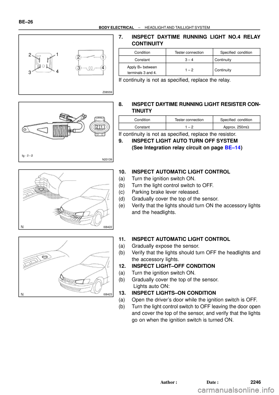
Z08559
1
2
341 2
43
N20139
1 2
I08422
I08423
BE±26
± BODY ELECTRICALHEADLIGHT AND TAILLIGHT SYSTEM
2246 Author�: Date�:
7. INSPECT DAYTIME RUNNING LIGHT NO.4 RELAY
CONTINUITY
ConditionTester connectionSpecified condition
Constant3 ± 4Continuity
Apply B+ between
terminals 3 and 4.1 ± 2Continuity
If continuity is not as specified, replace the relay.
8. INSPECT DAYTIME RUNNING LIGHT RESISTER CON-
TINUITY
ConditionTester connectionSpecified condition
Constant1 ± 2Approx. 250mW
If continuity is not as specified, replace the resistor.
9. INSPECT LIGHT AUTO TURN OFF SYSTEM
(See Integration relay circuit on page BE±14)
10. INSPECT AUTOMATIC LIGHT CONTROL
(a) Turn the ignition switch ON.
(b) Turn the light control switch to OFF.
(c) Parking brake lever released.
(d) Gradually cover the top of the sensor.
(e) Verify that the lights should turn ON the accessory lights
and the headlights.
11. INSPECT AUTOMATIC LIGHT CONTROL
(a) Gradually expose the sensor.
(b) Verify that the lights should turn OFF the headlights and
the accessory lights.
12. INSPECT LIGHT±OFF CONDITION
(a) Turn the ignition switch ON.
(b) Gradually cover the top of the sensor.
Lights auto ON:
13. INSPECT LIGHTS±ON CONDITION
(a) Open the driver's door while the ignition switch is OFF.
(b) Turn the light control switch to OFF leaving the door open
and cover the top of the sensor, and verify that the lights
go on when the ignition switch is turned ON.