Page 42 of 4592

AC0M6±02
N20277
P19978
± AIR CONDITIONINGCOMPRESSOR AND MAGNETIC CLUTCH
AC±41
2523 Author�: Date�:
REMOVAL
1. RUN ENGINE AT IDLE SPEED WITH A/C ON FOR
APPROX.10 MINUTES
2. STOP ENGINE
3. DISCONNECT NEGATIVE (±) TERMINAL CABLE
FROM BATTERY
4. DISCHARGE REFRIGERANT FROM REFRIGERATION
SYSTEM
5. REMOVE DRIVE BELT
(See page AC±17)
6. 1MZ±FE engine models:
REMOVE SUCTION HOSE
(a) Remove the suction hose clamping bolt.
(b) Disconnect the wire harness clamp.
(c) Loosen the nut and bolts and remove the suction hose.
NOTICE:
Cap the open fittings immediately to keep moisture or dirt
out of the system.
7. 1MZ±FE engine models:
DISCONNECT DISCHARGE HOSE
Remove the bolt and disconnect the hose.
NOTICE:
Cap the open fittings immediately to keep moisture or dirt
out of the system.
8. 1MZ±FE engine models:
REMOVE GENERATOR
(a) Disconnect the generator connector.
(b) Remove the nut, and disconnect the generator wire.
(c) Disconnect the wire harness from the clip.
(d) Remove the pivot bolt, plate washer, adjusting lock bolt
and generator.
Page 98 of 4592
PARK/NEUTRAL POSITION (PNP) SWITCH
1897 Author�: Date�:
PARK/NEUTRAL POSITION (PNP)
SWITCH
ON±VEHICLE REPAIR
1. REMOVE CONTROL SHAFT LEVER
(a) Rem")
Q10050
AX037±01
AX±4
± AUTOMATIC TRANSAXLE (A140E)PARK/NEUTRAL POSITION (PNP) SWITCH
1897 Author�: Date�:
PARK/NEUTRAL POSITION (PNP)
SWITCH
ON±VEHICLE REPAIR
1. REMOVE CONTROL SHAFT LEVER
(a) Remove the nut and control cable.
(b) Remove the nut, washer and control shaft lever.
2. DISCONNECT PARK/NEUTRAL POSITION SWITCH
CONNECTOR
3. REMOVE PARK/NEUTRAL POSITION SWITCH
(a) Pry off the lock washer and remove the nut.
(b) Remove the 2 bolts and park/neutral position switch.
4. INSTALL PARK/NEUTRAL POSITION SWITCH
(a) Install the park/neutral position switch with 2 bolts.
Torque: 5.4 N´m (55 kgf´cm, 48 in.´lbf)
(b) Install a new lock plate and the nut.
Torque: 6.9 N´m (70 kgf´cm, 61 in.´lbf)
(c) Bend claws on the lock plate to fix the nut.
(d) Adjust the park/neutral position switch.
(See page DI±389)
5. CONNECT PARK/NEUTRAL POSITION SWITCH CON-
NECTOR
6. INSTALL CONTROL SHAFT LEVER
(a) Install the control shaft lever, washer and nut.
Torque: 13 N´m (130 kgf´cm, 9 ft´lbf)
(b) Install the control cable and nut.
Torque: 15 N´m (150 kgf´cm, 11 ft´lbf)
Page 114 of 4592
AUTOMATIC TRANSAXLE UNIT
1913 Author�: Date�:
14. REMOVE EXHAUST MANIFOLD STAY
Remove the 2 bolts and exhaust manifold stay.
Torque: 42 N´m (")
Q10058
Q10059
Q00251
AX±20
± AUTOMATIC TRANSAXLE (A140E)AUTOMATIC TRANSAXLE UNIT
1913 Author�: Date�:
14. REMOVE EXHAUST MANIFOLD STAY
Remove the 2 bolts and exhaust manifold stay.
Torque: 42 N´m (430 kgf´cm, 31 ft´lbf)
15. REMOVE TRANSAXLE±TO±ENGINE BOLT
Torque: 66 N´m (670 kgf´cm, 48 ft´lbf)
16. REMOVE ENGINE HOOD
(a) Disconnect the washer pipe.
(b) Remove the 4 bolts and engine hood.
Torque: 14 N´m (145 kgf´cm, 10 ft´lbf)
17. RAISE AND SUPPORT VEHICLE SECURELY
18. REMOVE FRONT WHEELS
Torque: 103 N´m (1,050 kgf´cm, 76 ft´lbf)
19. REMOVE ENGINE UNDER COVER AND CENTER EN-
GINE UNDER COVER
20. DISCONNECT SHIFT CONTROL CABLE
(a) Remove the nut and disconnect the shift control cable
from the park/neutral position switch.
Torque: 15 N´m (150 kgf´cm, 11 ft´lbf)
(b) Remove the clip and disconnect the shift control cable
from the bracket.
21. REMOVE DIFFERENTIAL FLUID DRAIN PLUG AND
GASKET
HINT:
At the time of installation, please refer to the following item.
Replace the used gasket with a new gasket.
22. DRAIN DIFFERENTIAL FLUID
23. REMOVE LH AND RH FENDER APRON SEALS
24. REMOVE LH AND RH DRIVE SHAFTS
(See page SA±17)
Page 126 of 4592
AX03P±01
Q00229
Q06496
Q05727
Q04617
± AUTOMATIC TRANSAXLE (A541E)PARK/NEUTRAL POSITION (PNP) SWITCH
AX±5
1925 Author�: Date�:
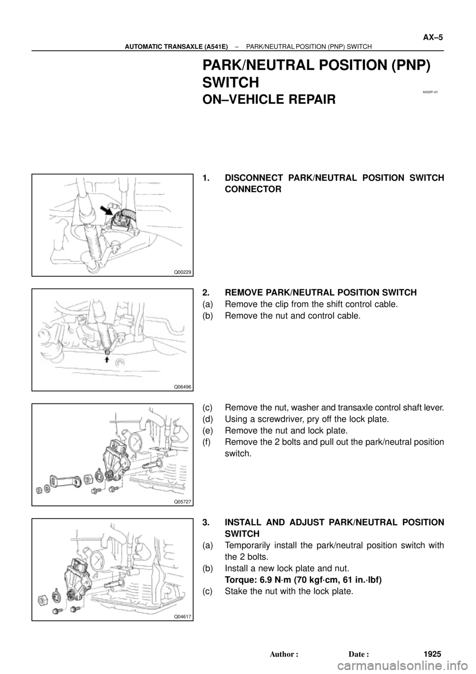
PARK/NEUTRAL POSITION (PNP)
SWITCH
ON±VEHICLE REPAIR
1. DISCONNECT PARK/NEUTRAL POSITION SWITCH
CONNECTOR
2. REMOVE PARK/NEUTRAL POSITION SWITCH
(a) Remove the clip from the shift control cable.
(b) Remove the nut and control cable.
(c) Remove the nut, washer and transaxle control shaft lever.
(d) Using a screwdriver, pry off the lock plate.
(e) Remove the nut and lock plate.
(f) Remove the 2 bolts and pull out the park/neutral position
switch.
3. INSTALL AND ADJUST PARK/NEUTRAL POSITION
SWITCH
(a) Temporarily install the park/neutral position switch with
the 2 bolts.
(b) Install a new lock plate and nut.
Torque: 6.9 N´m (70 kgf´cm, 61 in.´lbf)
(c) Stake the nut with the lock plate.
Page 127 of 4592
Z10304
Neutral
Basic
Line
Groove
Q04687
Q06496
AX±6
± AUTOMATIC TRANSAXLE (A541E)PARK/NEUTRAL POSITION (PNP) SWITCH
1926 Author�: Date�:
(d) Adjust the park/neutral position switch.
(See page DI±438)
(e) Install the transaxle control shaft lever and washer.
(f) Install and torque the nut.
Torque: 15 N´m (150 kgf´cm, 11 ft´lbf)
(g) Install the control cable and nut.
Torque: 15 N´m (150 kgf´cm, 11 ft´lbf)
(h) Install the clip to the shift control cable.
4. CONNECT PARK/NEUTRAL POSITION SWITCH CON-
NECTOR
5. TEST DRIVE VEHICLE
Page 145 of 4592
AUTOMATIC TRANSAXLE UNIT
1944 Author�: Date�:
12. REMOVE 2 FRONT SIDE ENGINE MOUNTING BOLTS
Torque:
TMC Made: 80 N´m (820 kgf´cm, 59")
Q06478
Q10286
Q06530
Q10038
AX±24
± AUTOMATIC TRANSAXLE (A541E)AUTOMATIC TRANSAXLE UNIT
1944 Author�: Date�:
12. REMOVE 2 FRONT SIDE ENGINE MOUNTING BOLTS
Torque:
TMC Made: 80 N´m (820 kgf´cm, 59 ft´lbf)
TMMK Made:
Green color bolt: 66 N´m (670 kgf´cm, 48 ft´lbf)
Silver color bolt: 44 N´m (440 kgf´cm, 32 ft´lbf)
13. REMOVE STARTER AND A/T SHIFT CABLE CLAMP
(a) Disconnect the connector and remove the nut.
(b) Remove the 2 bolts, starter and A/T shift cable clamp.
Torque: 39 N´m (400 kgf´cm, 29 ft´lbf)
14. REMOVE EXHAUST MANIFOLD BRACKET MOUNT-
ING BOLT
Torque:
Except California: 20 N´m (200 kgf´cm, 15 ft´lbf)
California: 34 N´m (350 kgf´cm, 25 ft´lbf)
15. REMOVE 5 TRANSAXLE±TO±ENGINE BOLTS AND
DISCONNECT GROUND TERMINAL
Torque: 66 N´m (670 kgf´cm, 48 ft´lbf)
16. REMOVE ENGINE HOOD
(a) Disconnect the washer pipe.
(b) Remove the 4 bolts and engine hood.
Torque: 26 N´m (265 kgf´cm, 19 ft´lbf)
17. RAISE AND SUPPORT VEHICLE SECURELY
18. REMOVE FRONT WHEELS
Torque: 103 N´m (1,050 kgf´cm, 76 ft´lbf)
19. REMOVE DIFFERENTIAL FLUID DRAIN PLUG AND
GASKET
HINT:
At the time of installation, please refer to the following item.
Replace the used gasket with a new gasket.
20. DRAIN DIFFERENTIAL FLUID
21. REMOVE LH AND RH ENGINE SIDE COVERS
22. REMOVE LH AND RH FRONT DRIVE SHAFTS
(See page SA±25)
Page 168 of 4592
AUTOMATIC TRANSAXLESERVICE SPECIFICATIONS ±
AX±16
Differential
Drive pinion preload (at starting) New bearing
Reused bearing
1.0 ± 1.6 N´m
10 ± 16 kgf´cm 8.7 ± 13.9 in.´lbf
0.5 ± 0.8 N´m
5 ± 8 kgf´cm 4.3 ± 6.9 in.´lbf
Total preload (at starting)
New bearing
Reused bearing
Add drive pinion preload
0.3 ± 0.4 N´m
2.9 ± 4.0 kgf´cm 2.5 ± 3.5 in.´lbf
0.1 ± 0.2 N´m
1.5 ± 2.0 kgf´cm 1.3 ± 1.7 in.´lbf
Pinion to side gear backlash0.05 ± 0.20 mm
0.0020 ± 0.0079 in.
Side gear thrust washer thickness
0.95 mm
0.0374 in.
1.00 mm
0.0394 in.
1.05 mm
0.0413 in.
1.10 mm
0.0433 in.
1.20 mm
0.0427 in.
Page 185 of 4592
AUTOMATIC TRANSAXLECOMPONENT PARTS REMOVAL ±
AX±15
SEPARATE BASIC SUBASSEMBLY
1. REMOVE PARK/NEUTRAL POSITION SWITCH
(a) Remove the manual shift lever.
(b) Pry off the lock washer and remove the manual valve
shaft nut.
(c) Remove the 2 bolts and pull out the park/neutral position
switch.
2. REMOVE UNION AND ELBOW
(a) Using the open end wrench, remove the union and elbow.
(b) Remove the O±rings from the union and elbow.
3. REMOVE SL SOLENOID
(a) Disconnect the connector.
(b) Remove the 2 bolts and SL solenoid.
4. REMOVE THROTTLE CABLE RETAINING PLATE
5. REMOVE SOLENOID WIRE RETAINING BOLT
6. REMOVE COVER
(a) Remove the 2 bolts and cover bracket.
AX0EW±02

 New bearing
Reused bearing
1.0 ± 1.6 N´m
10 ± 16 kgf´cm 8.7 ± 13.9 in.´lbf
0.5 ± 0.8 N´m
5 �")
 Remove the manual shift lever.
(b) Pry off the lock washer and remove the man")