Page 17 of 4592
AC0LN±02
Z19189
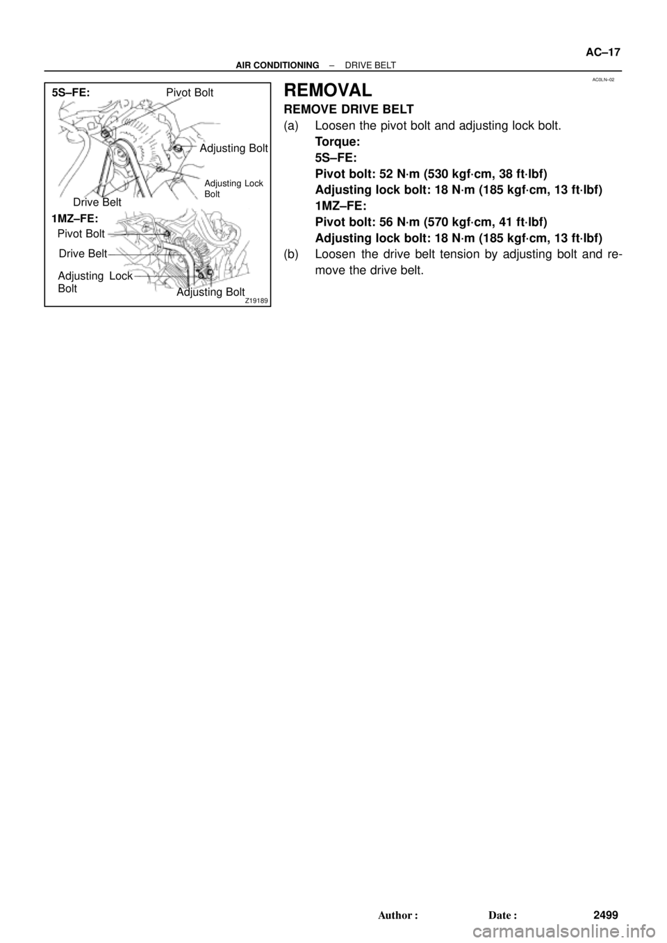
Pivot Bolt
Adjusting Bolt
Drive Belt
Pivot Bolt
Drive Belt
Adjusting Lock
Bolt
Adjusting Bolt 5S±FE:
1MZ±FE:
Adjusting Lock
Bolt
± AIR CONDITIONINGDRIVE BELT
AC±17
2499 Author�: Date�:
REMOVAL
REMOVE DRIVE BELT
(a) Loosen the pivot bolt and adjusting lock bolt.
Torque:
5S±FE:
Pivot bolt: 52 N´m (530 kgf´cm, 38 ft´lbf)
Adjusting lock bolt: 18 N´m (185 kgf´cm, 13 ft´lbf)
1MZ±FE:
Pivot bolt: 56 N´m (570 kgf´cm, 41 ft´lbf)
Adjusting lock bolt: 18 N´m (185 kgf´cm, 13 ft´lbf)
(b) Loosen the drive belt tension by adjusting bolt and re-
move the drive belt.
Page 22 of 4592
AC0LS±02
I07049
Suction TubeLiquid Tube
Piping Clamp
Liquid Tube
Suction Hose
Discharge Hose
N´m (kgf´cm, ft´lbf) : Specified torque
32 (330, 24)
5.4 (55, 48 in.´lbf)
5.4 (55, 48 in.´lbf)
10 (100, 7)
10 (100, 7)
10 (100, 7)
14 (140, 10)
5.4 (55, 48 in.´lbf)
AC±22
± AIR CONDITIONINGREFRIGERANT LINE
2504 Author�: Date�:
LOCATION
Page 23 of 4592
AC0LT±03
± AIR CONDITIONINGREFRIGERANT LINE
AC±23
2505 Author�: Date�:
REPLACEMENT
1. DISCHARGE REFRIGERANT FROM REFRIGERATION SYSTEM
2. REPLACE FAULTY TUBE OR HOSE
NOTICE:
Cap the open fittings immediately to keep moisture or dirt out of the system.
3. TIGHTEN JOINT OF BOLT OR NUT TO SPECIFIED TORQUE
NOTICE:
Connections should not be torqued tighter than the specified torque.
Part tightenedN´mkgf´cmft´lbf
Receiver x Liquid tube5.45548 in.´lbf
Condenser x Discharge hose101007
Condenser x Liquid tube1414010
Compressor x Discharge hose101007
Compressor x Suction hose101007
Expansion valve x Evaporator5.45548 in.´lbf
Suction line (Piping joint)3233024
Suction line (Block joint)101007
4. EVACUATE AIR FROM REFRIGERATION SYSTEM AND CHARGE WITH REFRIGERANT
Specified amount : 800 ± 50g (28.22 ± 1.76 oz.)
5. INSPECT FOR LEAKAGE OF REFRIGERANT
Using a gas leak detector, check for leakage of refrigerant.
6. INSPECT AIR CONDITIONING OPERATION
Page 24 of 4592
AC21U±01
N20296
N20294
AC±24
± AIR CONDITIONINGAIR CONDITIONING UNIT
2506 Author�: Date�:
AIR CONDITIONING UNIT
ON±VEHICLE INSPECTION
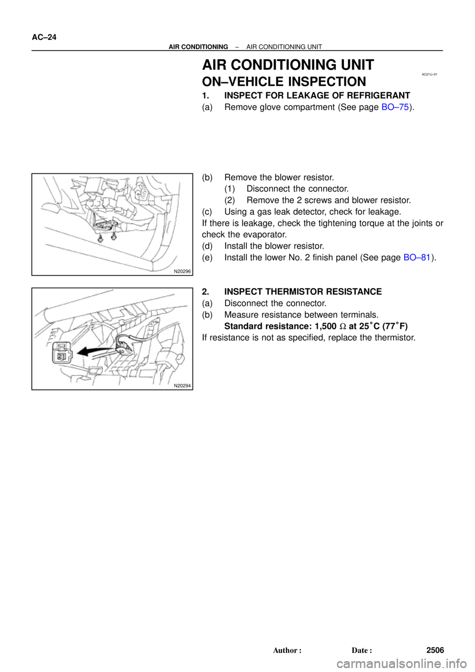
1. INSPECT FOR LEAKAGE OF REFRIGERANT
(a) Remove glove compartment (See page BO±75).
(b) Remove the blower resistor.
(1) Disconnect the connector.
(2) Remove the 2 screws and blower resistor.
(c) Using a gas leak detector, check for leakage.
If there is leakage, check the tightening torque at the joints or
check the evaporator.
(d) Install the blower resistor.
(e) Install the lower No. 2 finish panel (See page BO±81).
2. INSPECT THERMISTOR RESISTANCE
(a) Disconnect the connector.
(b) Measure resistance between terminals.
Standard resistance: 1,500 W at 25°C (77°F)
If resistance is not as specified, replace the thermistor.
Page 26 of 4592
I07051
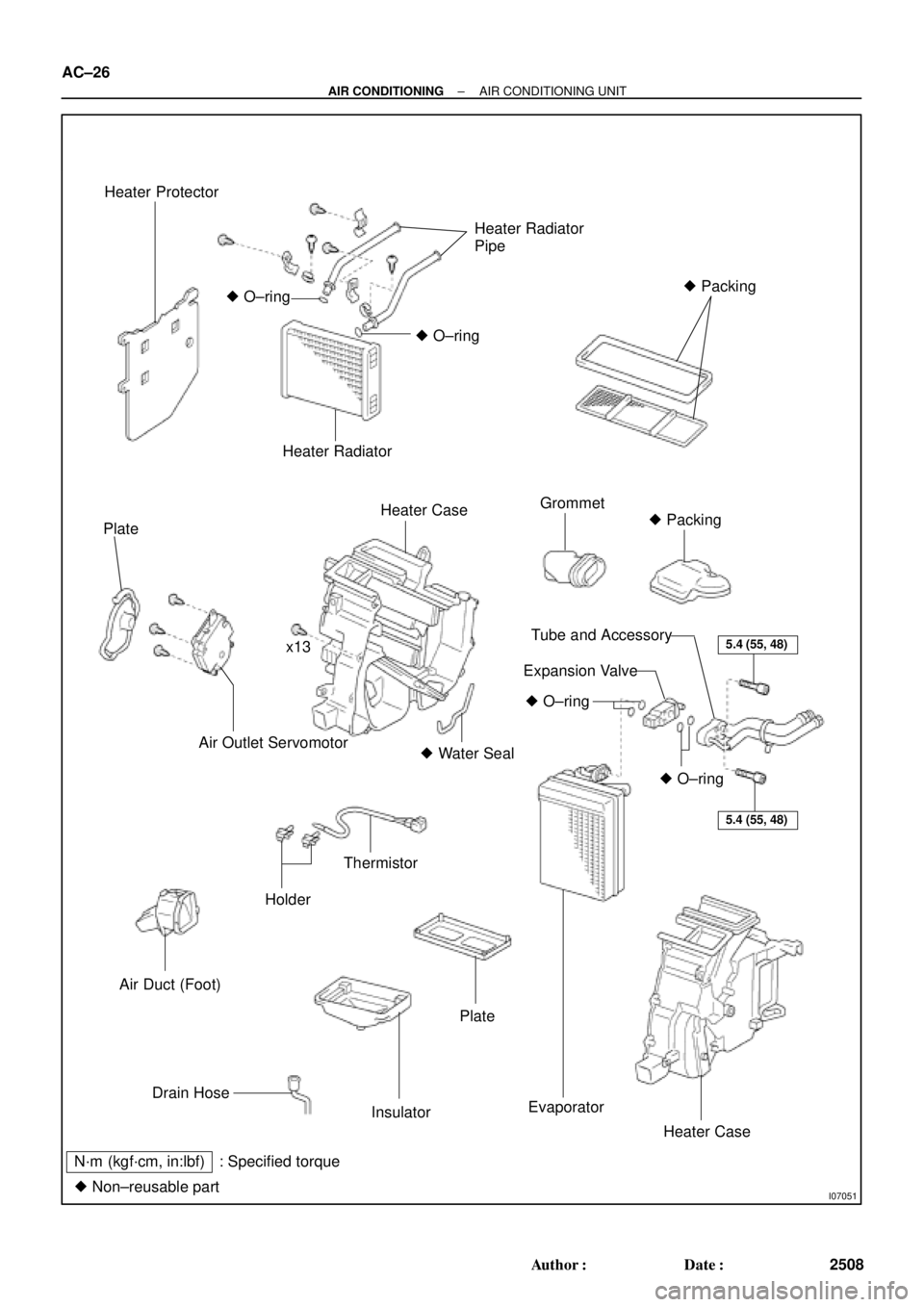
Heater Protector
Heater Radiator
Pipe
� Packing
� O±ring
� O±ring
Heater Radiator
Plate
Heater CaseGrommet
� Packing
x13
Air Outlet Servomotor� Water Seal
Air Duct (Foot)
Holder
Thermistor
5.4 (55, 48)
5.4 (55, 48)
� O±ring
� O±ring
Tube and Accessory
Expansion Valve
Drain Hose
Insulator
Plate
Evaporator
Heater Case
N´m (kgf´cm, in:lbf) : Specified torque
� Non±reusable part
AC±26
± AIR CONDITIONINGAIR CONDITIONING UNIT
2508 Author�: Date�:
Page 32 of 4592
N20283
N20245
Pin
Pin AC±32
± AIR CONDITIONINGAIR CONDITIONING UNIT
2514 Author�: Date�:
(e) Lubricate 2 new O±rings with compressor oil and install
the expansion valve.
(f) Install the expansion valve with the tubes to evaporator
with the 2 bolts.
Torque: 5.4 N´m (55 kgf´cm, 48 in.´lbf)
NOTICE:
When installing the expansion valve, take care so that the
packing is not jammed with the evaporator.
(g) Peel off the remaining packing paper and apply the pack-
ing to expansion valve.
4. INSTALL HEATER RADIATOR
(a) Install the heater radiator to heater case.
(b) Install the heater radiator pipe with 2 clips.
(c) Install the 3 clamps with the 3 screws.
5. INSTALL MODE SERVOMOTOR
(a) Install the servomotor with the 3 screws.
(b) Insert the drain of the plate to the pin and install plate.
Page 41 of 4592
AC0M5±02
I03331
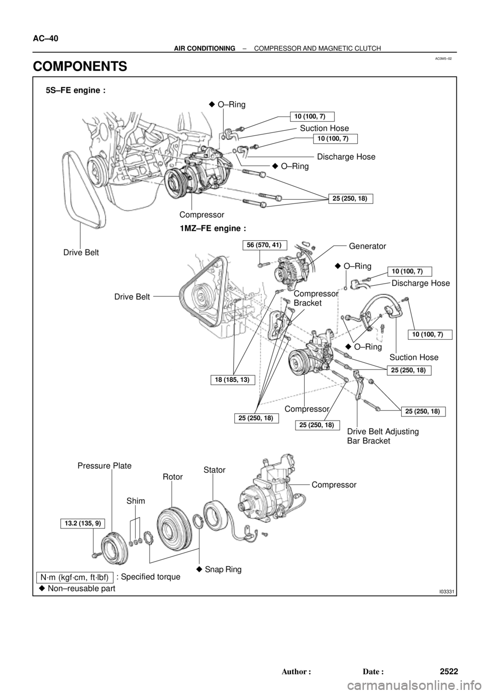
5S±FE engine :
Drive BeltCompressor� O±Ring
Suction Hose
Discharge Hose
10 (100, 7)
10 (100, 7)
� O±Ring
25 (250, 18)
1MZ±FE engine :
� O±Ring
Drive Belt
Drive Belt Adjusting
Bar BracketGenerator
Discharge Hose
10 (100, 7)
10 (100, 7)
25 (250, 18)
Compressor
25 (250, 18)
25 (250, 18)
ShimSuction Hose � O±Ring
25 (250, 18)
56 (570, 41)
18 (185, 13)
13.2 (135, 9)
Rotor Pressure Plate
: Specified torque
N´m (kgf´cm, ft´lbf)Stator
Compressor
� Snap Ring
� Non±reusable part
Compressor
Bracket AC±40
± AIR CONDITIONINGCOMPRESSOR AND MAGNETIC CLUTCH
2522 Author�: Date�:
COMPONENTS
Page 44 of 4592
AC0M7±02
AC0943
SST
AC0944
SST
AC0945
SST
AC0946
Shim
Pressure
Plate
AC0947
SST
± AIR CONDITIONINGCOMPRESSOR AND MAGNETIC CLUTCH
AC±43
2525 Author�: Date�:
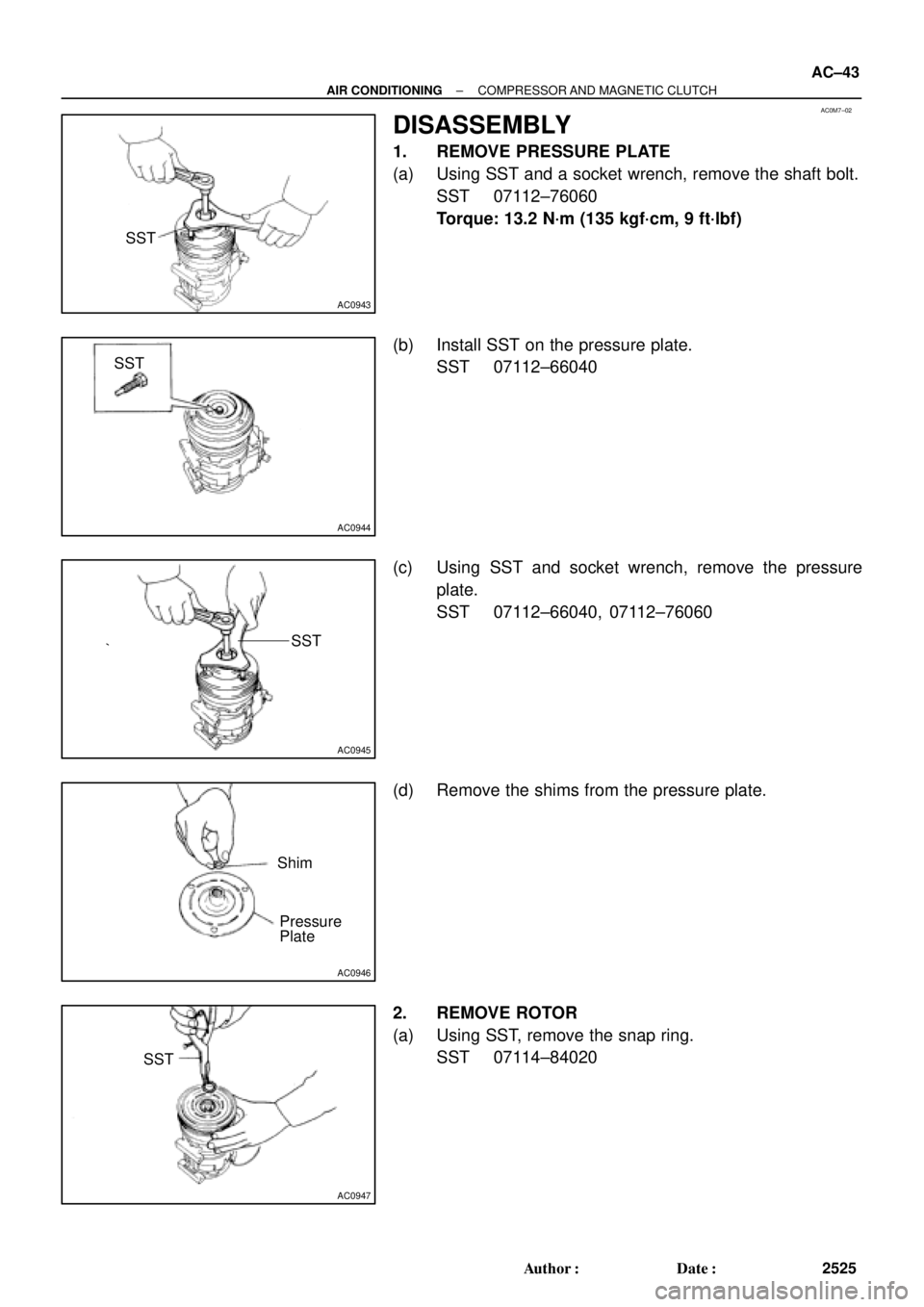
DISASSEMBLY
1. REMOVE PRESSURE PLATE
(a) Using SST and a socket wrench, remove the shaft bolt.
SST 07112±76060
Torque: 13.2 N´m (135 kgf´cm, 9 ft´lbf)
(b) Install SST on the pressure plate.
SST 07112±66040
(c) Using SST and socket wrench, remove the pressure
plate.
SST 07112±66040, 07112±76060
(d) Remove the shims from the pressure plate.
2. REMOVE ROTOR
(a) Using SST, remove the snap ring.
SST 07114±84020
 : Specified torque
32 (330, 24)
5.4 (55, 48 in.´lbf)
5.4 (55, 48 in.´lbf)
10 (10")