Page 872 of 4592
BO0LE±01
N22588
121
N21430
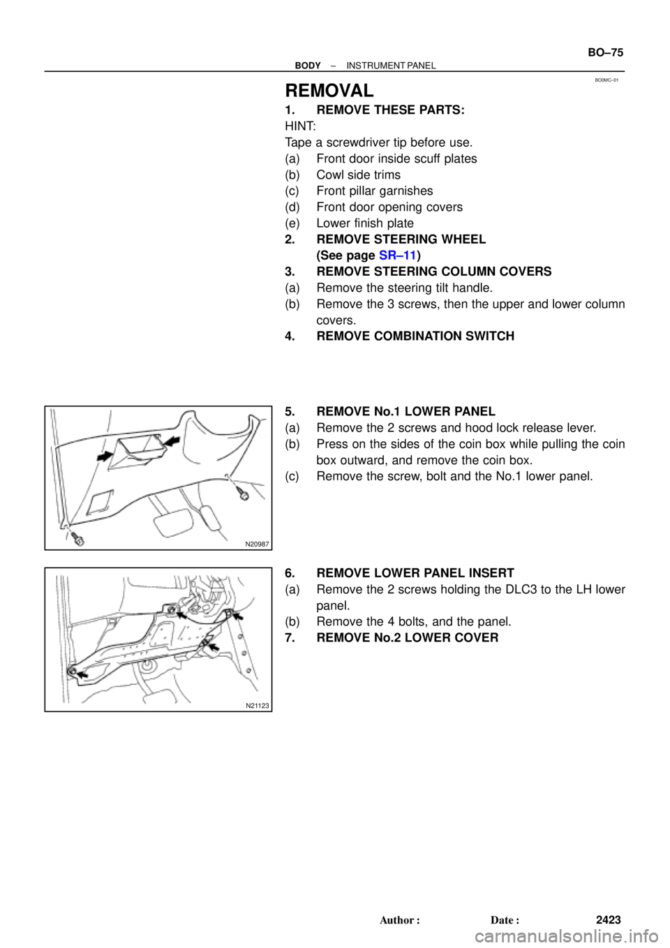
: 4 Clips
N22591
BO±28
± BODYLUGGAGE COMPARTMENT DOOR AND HINGE
2376 Author�: Date�:
REMOVAL
1. REMOVE LUGGAGE COMPARTMENT DOOR TRIM
2. REMOVE LUGGAGE COMPARTMENT DOOR
(a) Disconnect the connector.
(b) Using a clip remover, disconnect the clamps.
(c) Remove the 4 bolts and door.
Torque: 8.0 N´m (80 kgf´cm, 71 in.´lbf)
3. REMOVE THESE PARTS:
(a) Luggage compartment floor mat
(b) LH and RH rear floor finish side plates
(c) Inner cover trims
(d) Rear seat
(e) Room partition trims
4. REMOVE HIGH±MOUNTED STOP LIGHT
(a) Push on the both side of the cover to release the claws by
your hand and remove the cover as shown in the illustra-
tion.
(b) Remove the 2 bolts and stop light, then disconnect the
connector.
5. REMOVE ROOF SIDE INNER GARNISH
(a) Remove the clip.
(b) Using a screwdriver, pry loose and remove the garnish.
HINT:
Tape the screwdriver tip before use.
6. REMOVE PACKAGE TRAY TRIM
7. REMOVE TORSION BAR
(a) Remove the torsion bar from the center bracket.
Page 877 of 4592
BO0LI±01
H01754
H01755
H01756
N21430
: 4 clips
± BODYLUGGAGE COMPARTMENT DOOR AND HINGE
BO±33
2381 Author�: Date�:
INSTALLATION
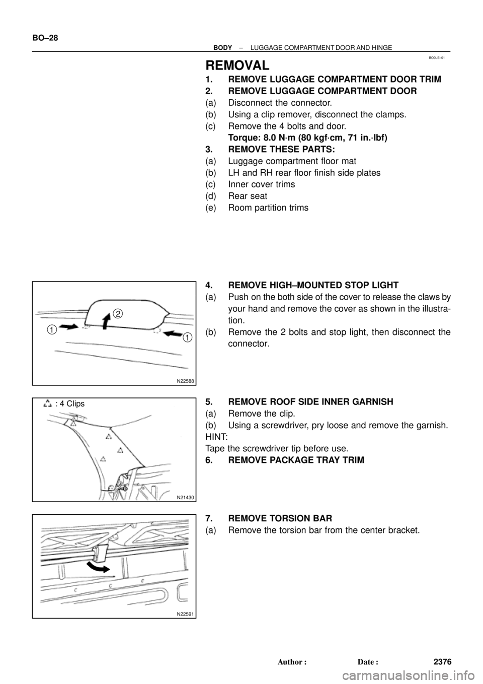
1. INSTALL TORSION BAR
(a) Insert the torsion bar into the bracket.
HINT:
The center bracket opening is the nominal position of the tor-
sion bar.
If needed, move the torsion bar to the upper or lower hole to pro-
vide the correct luggage door lift.
(b) Install the SST onto the torsion bar of the hinge side.
SST 09804±24010
(c) Slowly lift the torsion bar with the SST and place it in the
torsion bar bracket.
(d) Slowly push the SST down and install the torsion bar to
the hinge.
(e) Slowly lift the SST and install the torsion bar.
(f) Install the torsion bar to the center bracket.
(g) Repeat for the other side.
2. INSTALL PACKAGE TRAY TRIM
3. INSTALL ROOF SIDE INNER GARNISH
4. INSTALL HIGH MOUNTED STOP LIGHT
5. INSTALL THESE PARTS:
(a) Room partition trims
(b) Rear seat
(c) Inner cover trims
(d) LH and RH rear floor finish side plates
(e) Luggage compartment floor mat
6. INSTALL LUGGAGE COMPARTMENT DOOR
(a) Install the door with 4 bolts.
(b) Install clamps.
(c) Connect the connector.
7. INSTALL LUGGAGE COMPARTMENT DOOR TRIM
Page 894 of 4592
BO0LS±01
N21020
3 Clips
1 Clip
N22588
N21021
4 Clips
N21121
N20985
BO±50
± BODYBACK WINDOW GLASS
2398 Author�: Date�:
REMOVAL
1. REMOVE REAR SEAT CUSHION AND SEATBACKS
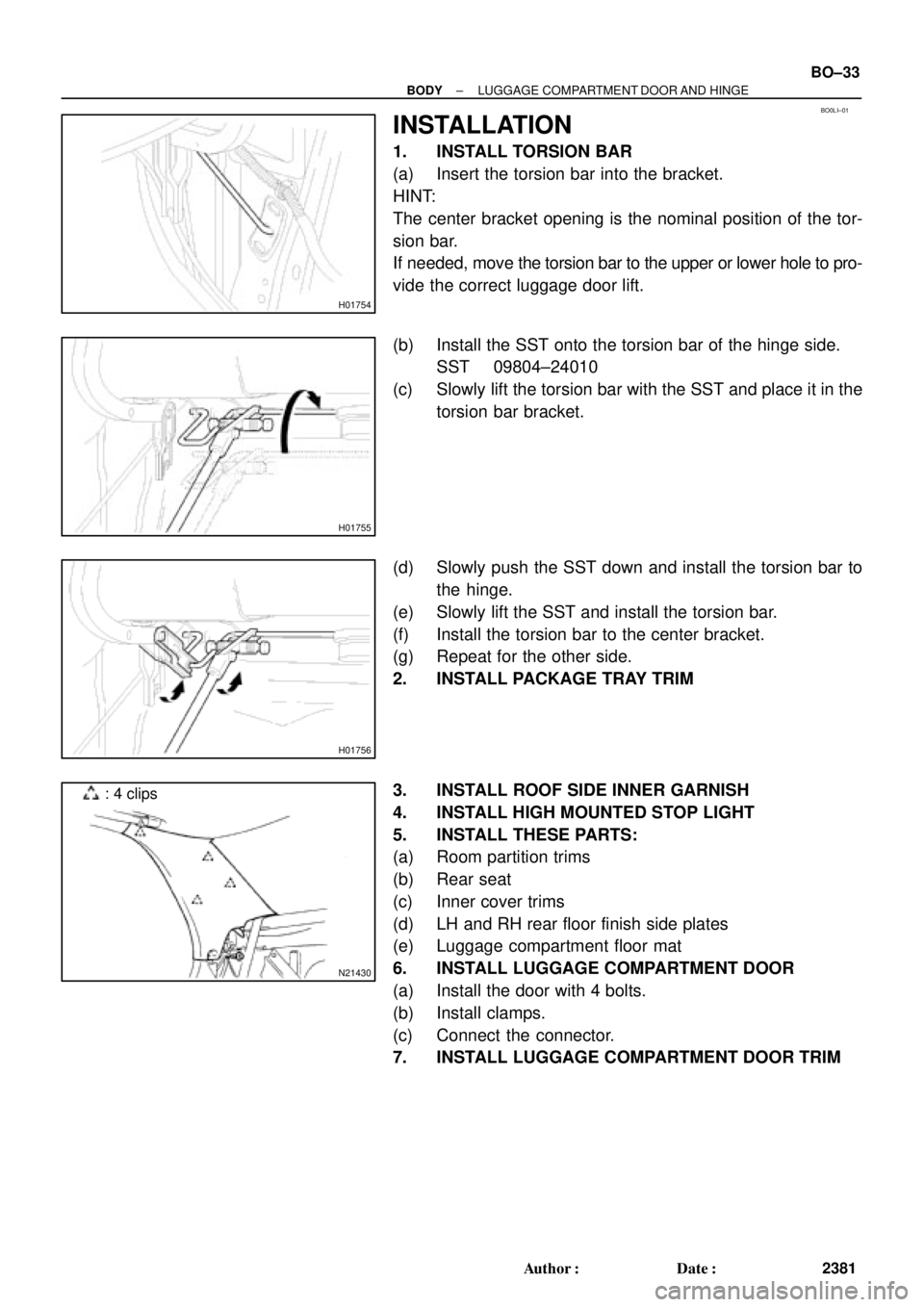
2. REMOVE ROOF SIDE INNER GARNISHES
(a) Remove the clips.
(b) Pull the garnish to remove it.
3. REMOVE HIGH±MOUNTED STOP LIGHT
(a) Push on the both side of the cover to release the claws by
your hand and remove the cover as shown in the illustra-
tion.
(b) Remove the 2 bolts and stop light, then disconnect the
connector.
4. REMOVE PACKAGE TRAY TRIM
(a) Remove the bolts holding the rear seat belt lower side to
the body.
(b) Remove the seat belts with seat belt hole covers from the
package trim.
(c) Remove the trim by pulling forward.
5. REMOVE ROOM PARTITION TRIMS
Remove the 6 clips and room partition trims.
6. REMOVE THESE PARTS
(a) Assist grips.
(b) Rear side of roof headlining.
7. DISCONNECT DEFOGGER WIRE CONNECTORS
8. REMOVE BACK WINDOW MOULDING
Using a knife, cut off the moulding as shown.
NOTICE:
Do not damage the body with the knife.
9. REMOVE BACK WINDOW GLASS
Remove the glass in the same way as windshield.
(See page BO±43)
Page 896 of 4592
BO±52
± BODYBACK WINDOW GLASS
2400 Author�: Date�:
(d) Room partition trims
(e) Seat belt lower side bolts
Torque: 42 N´m (420 kgf´cm, 31 ft´lbf)
(f) High±mounted stop light
(g) Roof side inner garnish
(h) Rear seatbacks and seat cushion
Torque: 18 N´m (185 kgf´cm, 13 ft´lbf)
Page 919 of 4592
BO0MC±01
N20987
N21123
± BODYINSTRUMENT PANEL
BO±75
2423 Author�: Date�:
REMOVAL
1. REMOVE THESE PARTS:
HINT:
Tape a screwdriver tip before use.
(a) Front door inside scuff plates
(b) Cowl side trims
(c) Front pillar garnishes
(d) Front door opening covers
(e) Lower finish plate
2. REMOVE STEERING WHEEL
(See page SR±11)
3. REMOVE STEERING COLUMN COVERS
(a) Remove the steering tilt handle.
(b) Remove the 3 screws, then the upper and lower column
covers.
4. REMOVE COMBINATION SWITCH
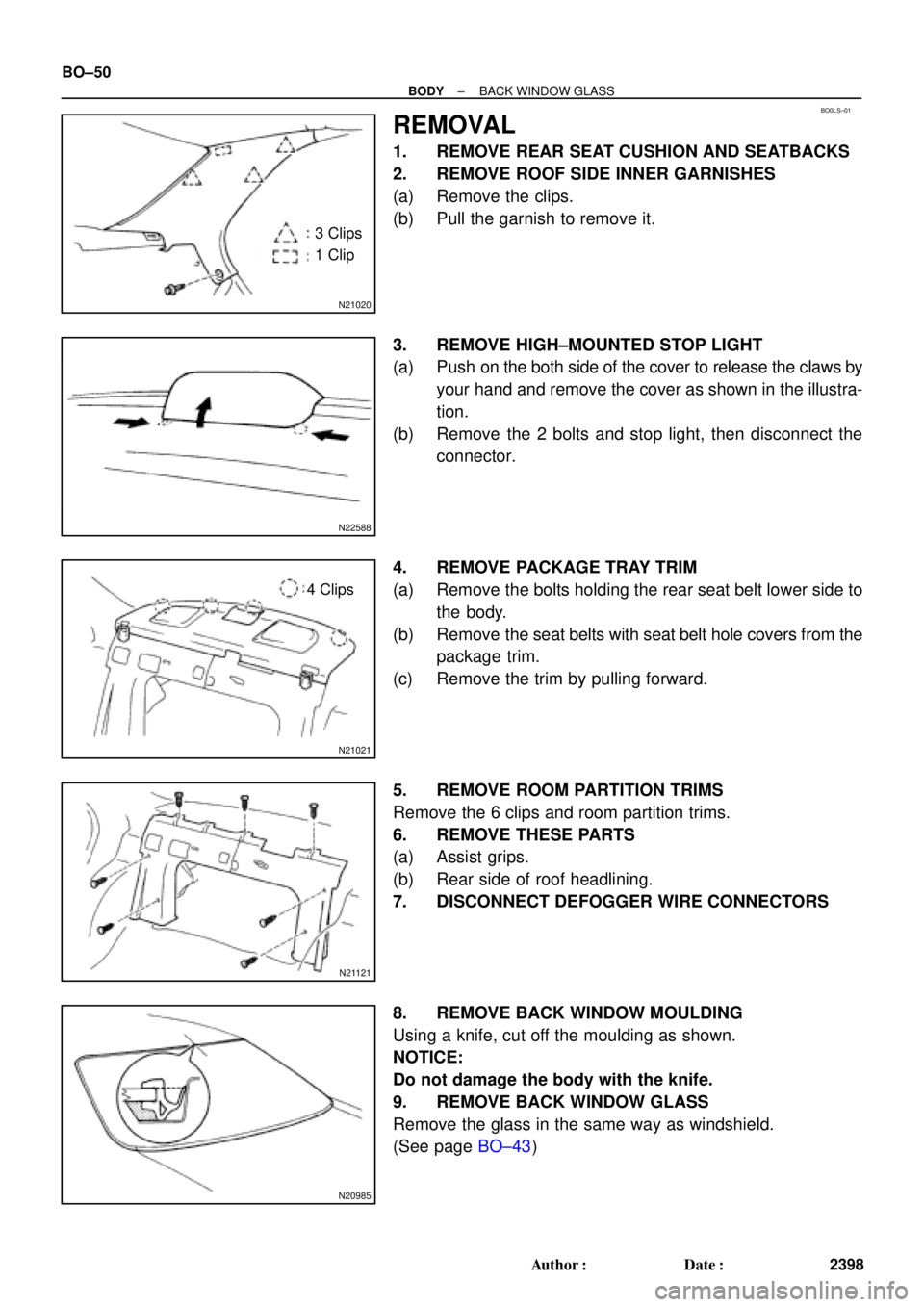
5. REMOVE No.1 LOWER PANEL
(a) Remove the 2 screws and hood lock release lever.
(b) Press on the sides of the coin box while pulling the coin
box outward, and remove the coin box.
(c) Remove the screw, bolt and the No.1 lower panel.
6. REMOVE LOWER PANEL INSERT
(a) Remove the 2 screws holding the DLC3 to the LH lower
panel.
(b) Remove the 4 bolts, and the panel.
7. REMOVE No.2 LOWER COVER