Page 855 of 4592
BO0L2±01
H01975
Door Lock
Cylinder
Outside Handle Front Door Belt Moulding
Door Glass
Door FrameFront Door Upper Moulding
Outside
Rear View
Mirror
Door Glass
Run
5.5 (55, 49 in.´lbf)
5.5 (55, 49 in.´lbf)
5.0 (50, 43 in.´lbf)�
Door Lock
23 (230, 17)
Window Regulator
8.0 (80, 69 in.´lbf)
Door Hinge
X6
7.5 (75, 66 in.´lbf)
Regulator
Motor
X3
31 (310, 22)
26 (260, 19)
8.0 (80, 71 in.´lbf)
30 (300, 22)
31 (310, 22)
Door
Check
Door Hinge
26 (260, 19)
Speaker
Power Window Switch Rear Lower
FrameFront Lower
FrameFront Window Upper
Garnish
Inside Handle Bezel
3.5 (35, 31 in.´lbf)
Driver's Side:
Regulator
Motor
Ptdt
N´m (kgf´cm, ft´lbf) : Specified torqueInside Handle
Door Trim
� Precoated part Door Lock StrikerService Hole Cover
± BODYFRONT DOOR
BO±11
2359 Author�: Date�:
FRONT DOOR
COMPONENTS
Page 856 of 4592

(b)(a)
BO±12
± BODYFRONT DOOR
2360 Author�: Date�:
DISASSEMBLY
1. w/o Power Window:
REMOVE REGULATOR HANDLE
Pull off the snap ring with a shop rag an")
BO0L3±01
H01738
N20968
N210034 Clips
N20969
(c)
(b)(a)
BO±12
± BODYFRONT DOOR
2360 Author�: Date�:
DISASSEMBLY
1. w/o Power Window:
REMOVE REGULATOR HANDLE
Pull off the snap ring with a shop rag and remove the regulator
handle and plate.
HINT:
At the time of assembly, please refer to the following item.
With the door window fully closed, install the plate and the regu-
lator handle with the snap ring.
2. REMOVE INSIDE HANDLE BEZEL
(a) Using a screwdriver, pry open the screw cover and re-
move the screw.
HINT:
Tape the screwdriver tip before use.
(b) Using a screwdriver, pry out the bezel.
HINT:
Tape the screwdriver tip before use.
3. REMOVE FRONT WINDOW UPPER GARNISH
4. REMOVE DOOR TRIM
(a) Using a screwdriver, remove the screw caps.
HINT:
Tape the screwdriver tip before use.
(b) Remove the 2 clips, 2 screws and 2 bolts.
(c) Insert a screwdriver between the door and door trim to pry
out.
(d) Pull the trim upward to remove it, then remove the power
window switch and disconnect the harness connector.
5. REMOVE THESE PARTS:
(a) Outside rear view mirror
Torque: 5.5 N´m (55 kgf´cm, 49 in.´lbf)
(b) Speaker
6. REMOVE DOOR INSIDE HANDLE
(a) Remove the screw and pull the handle forward.
Torque: 3.5 N´m (35 kgf´cm, 31 in.´lbf)
(b) Remove the link from the clamp.
(c) Remove the inside handle from the ends of the 2 links.
7. REMOVE SERVICE HOLE COVER
Remove the grommet, then remove the service hole cover.
Page 867 of 4592
BO0LA±01
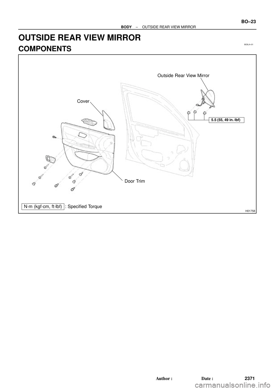
H01758
Outside Rear View Mirror
Cover
Door Trim
N´m (kgf´cm, ft´lbf) : Specified Torque
5.5 (55, 49 in.´lbf)
± BODYOUTSIDE REAR VIEW MIRROR
BO±23
2371 Author�: Date�:
OUTSIDE REAR VIEW MIRROR
COMPONENTS
Page 868 of 4592

H01759
UTA: IMI:
TOKAIRIKA:
Mirror
Mirror Shell
Gasket
Mirror w/case
Wire Retainer
Mirror w/case
Clip X4
BO0LB±01
H01760
Mirror w/caseGasket
Mirror HousingWire Retainer
H01761
Pivot Mirror Housing Forward
H01762
Mirror
Glass
Terminals
Mirror CaseScraper BO±24
± BODYOUTSIDE REAR VIEW MIRROR
2372 Author�: Date�:
DISASSEMBLY
1. IDENTIFY OUTSIDE REAR VIEW MIRROR
(a) w/ Power Rear View Mirror:
UTA:
The mirror moves smoothly when pressing the end of the
mirror inward.
(b) w/ Power Rear View Mirror:
IMI:
The mirror stutters when pressing the end of the mirror in-
ward.
(c) w/ Power Rear View Mirror:
TOKAIRIKA:
Equipped only on vehicles manufactured by TMC.
(d) w/o Power Rear View Mirror:
Mirrors manufactured by IMI
2. UTA:
DISASSEMBLE OUTSIDE REAR VIEW MIRROR
(a) Disconnect the battery.
(b) Press the inboard end of the mirror inward to access the
rear of the mirror w/case assembly.
(c) Unlatch both ends of the wire retainer, then remove the
mirror parts from the mirror housing.
NOTICE:
Be careful not to damage the wires on heated mirrors. Dis-
connect the wires from the back side of the heater.
3. IMI:
DISASSEMBLE OUTSIDE REAR VIEW MIRROR
(a) w/Heated Mirrors:
Disconnect the battery.
(b) Protect the door surface.
(c) Pivot the mirror housing to the forward position.
(d) Insert a scraper between the mirror and the case to re-
move the mirror.
NOTICE:
Be careful not to damage the wires on heated mirrors. Dis-
connect the wires from the back side of the heater.
Page 869 of 4592
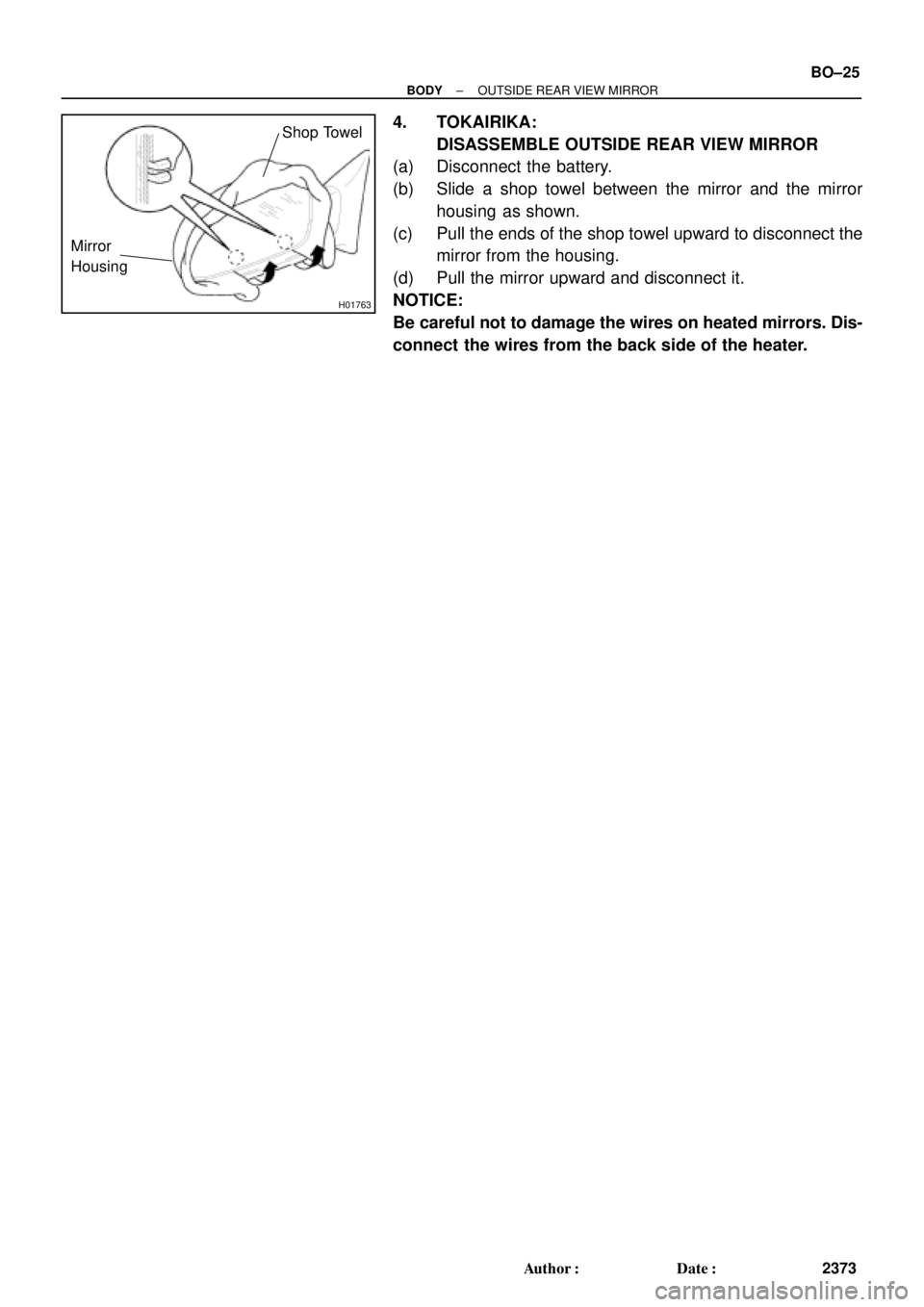
H01763
Mirror
Housing
Shop Towel
± BODYOUTSIDE REAR VIEW MIRROR
BO±25
2373 Author�: Date�:
4. TOKAIRIKA:
DISASSEMBLE OUTSIDE REAR VIEW MIRROR
(a) Disconnect the battery.
(b) Slide a shop towel between the mirror and the mirror
housing as shown.
(c) Pull the ends of the shop towel upward to disconnect the
mirror from the housing.
(d) Pull the mirror upward and disconnect it.
NOTICE:
Be careful not to damage the wires on heated mirrors. Dis-
connect the wires from the back side of the heater.
Page 870 of 4592

H01764
Gasket
Mirror w/case
Mirror HousingWire Retainer
BO0LC±01
H01765
50±60 mm
H01766
Glass
Case
Edge
H01767
Claw BClaw A BO±26
± BODYOUTSIDE REAR VIEW MIRROR
2374 Author�: Date�:
REASSEMBLY
1. UTA:
ASSEMBLE OUTSIDE REAR VIEW MIRROR
(a) w/Heated Mirrors:
Connect the heater wires.
(b) Install the wire retainer onto the mirror w/case assembly,
then press the mirror firmly into place to engage the 6 lugs
of the wire retainer.
NOTICE:
Pull the mirror edges to confirm the wire retainer lugs com-
pletely engage with the mirror housing.
(c) Reconnect the battery, then operate the mirror to its full
stop position.
2. IMI:
ASSEMBLE OUTSIDE REAR VIEW MIRROR
(a) From a distance of 50±60 mm, use a heat gun or hair dry-
er to heat the edge of the mirror case until the mirror case
becomes soft.
CAUTION:
Use extreme caution when using a heat gun or hair dryer.
Holding it too close can melt the mirror case.
(b) w/ Heated Mirrors:
Connect the heater wires.
(c) Before the the case cools down, position and snap the
new mirror glass into the case.
NOTICE:
Verify the glass case edge completely surrounds the mirror
glass.
(d) Allow the case to cool down before moving the mirror
back to its operating position.
(e) Recheck the fit between the glass and the case.
(f) Reconnect the battery, then operate the mirror to its full
stop position.
3. TOKAIRIKA:
ASSEMBLE OUTSIDE REAR VIEW MIRROR
(a) w/ Heated Mirrors:
Connect the heater wires.
(b) Connect the claws (A) and install the mirror into the mirror
housing.
(c) Push the mirror inward to connect the claws (B) onto the
mirror housing.
(d) Reconnect the battery, then operate the mirror to its full
stop position.
Page 886 of 4592
BO0LO±01
N20947
Front Pillar GarnishWeatherstripSun VisorInside Rear
View Mirror Map Light Assem-
bly
Sun Visor
Holder
Windshield
Glass
Windshield Upper Moulding
Weatherstrip Stopper
Dam
Windshield
Outside
Moulding
Wiper Arm
Cowl Louver RH
Weatherstrip
24 (245, 18)
Cowl Louver LHWindshield
Outside
MouldingFront Pillar Garnish
Hood
N´m (kgf´cm, ft´lbf): Specified torque BO±42
± BODYWINDSHIELD
2390 Author�: Date�:
WINDSHIELD
COMPONENTS
Page 887 of 4592
 Inner rear view mirror
(b) Sun visors and holders
(c) Map light assembly
(d) Front pilla")
BO0LP±01
N20982
N20983
BO5232
± BODYWINDSHIELD
BO±43
2391 Author�: Date�:
REMOVAL
1. REMOVE THESE PARTS:
(a) Inner rear view mirror
(b) Sun visors and holders
(c) Map light assembly
(d) Front pillar garnishes
(e) Hood
(f) Wiper arms
(g) Cowl louvers
(h) Weatherstrips
2. REMOVE WEATHERSTRIP
Remove the weatherstrip by pulling.
HINT:
Remove only the front half of weatherstrip.
3. REMOVE WINDSHIELD OUTSIDE MOULDING
(a) Using a drill of less than ù 5.0 mm (0.20 in.), drill out the
rivet heads and remove the moulding.
(b) Using a vacuum cleaner, remove the drill rivet and their
dust from the inside of the door.
CAUTION:
The cut rivet and rivet cutter will be not, avoid touching
them.
NOTICE:
Do not jiggle the rivet cutter while cutting.You may enlarge
the rivet hole or damage the rivet cutter.
HINT:
Do not drill the body.
Sealant may cause the moulding to stick to the glass. If neces-
sary, separate from the glass using a knife.
4. REMOVE WINDSHIELD UPPER MOULDING
Using a knife, cut off the moulding as shown.
NOTICE:
Do not damage the body with the knife.
5. REMOVE WINDSHIELD GLASS
(a) Push piano wire through between the body and glass
from the interior.
(b) Tie both wire ends to a wooden block or a similar object.
HINT:
Apply adhesive tape to the outer surface to prevent scratching.

5.5 (55, 49 in")